
$38 – $72
PV-DC / Single-Phase Input, Three-Phase Output | 0.75–4kW | MOQ: 1 Piece | CE Certified
Product Overview
The LAKINELE solar S3 drive combines MPPT solar tracking with single-phase 220V input and three-phase output. It runs a pump directly from PV (with grid fallback as backup) from 0.75kW to 4kW — no battery required.
We verified the platform on our bench: sensorless vector holds 180% torque at 0.5Hz with speed accuracy of ±0.5%, so it starts under load without tripping. Best for: Solar pumping with single-phase backup, three-phase motor.
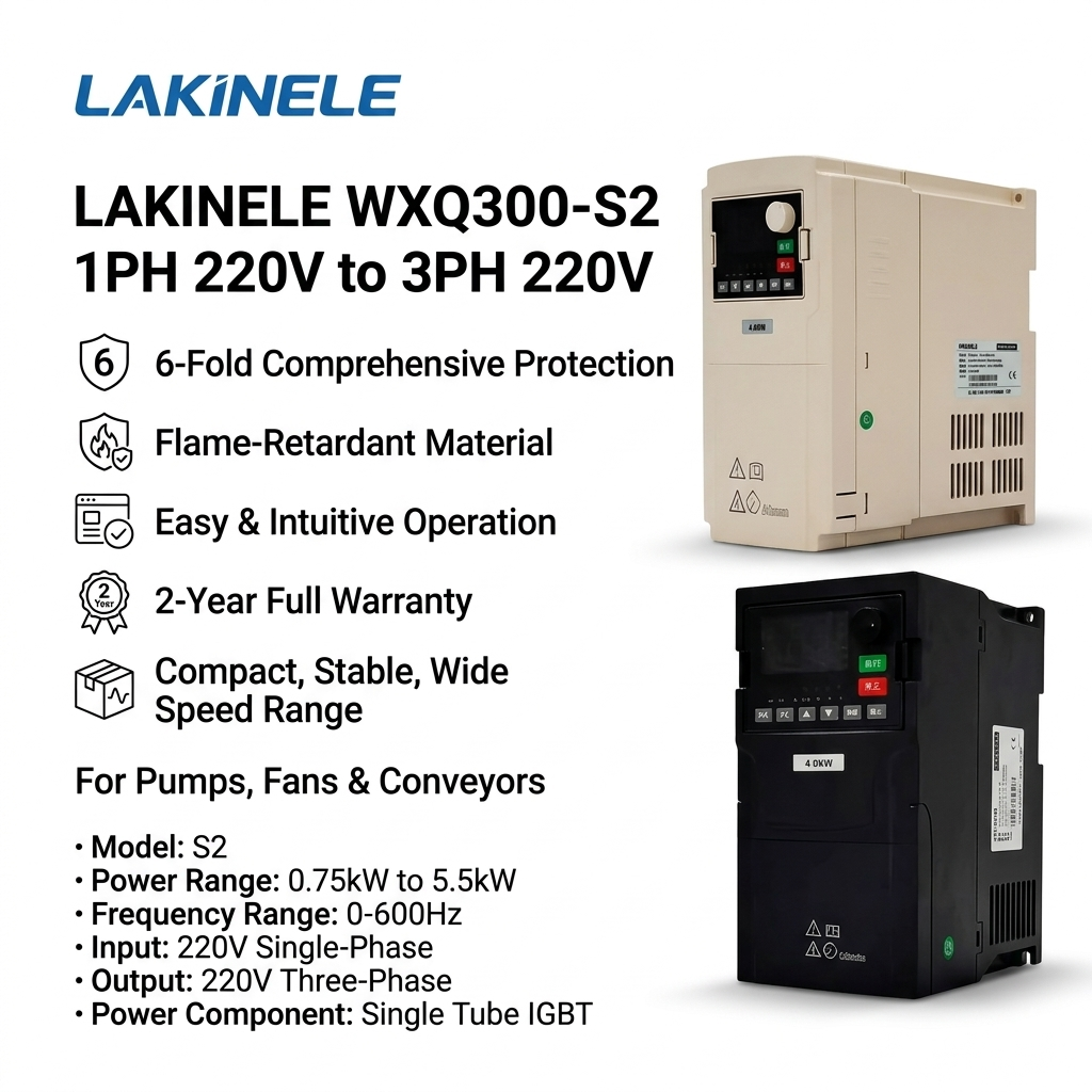
Key Features
180% Starting Torque
0.5Hz / 180% in sensorless vector — starts loaded machines
±0.5% Accuracy
1:100 speed range, 0.01Hz digital resolution
RS485 Modbus RTU
Built-in for PLC / SCADA control and monitoring
Built-in PID
Pressure, flow & temperature closed-loop control
Full Protection
OC, OV, UV, OH, OL, phase loss & ground fault
Full-Load Aged
100% load-tested before shipment
Models, Ratings & Dimensions
| Model | Rated Current | Dimensions (H×W×D mm) | Shell Type |
|---|---|---|---|
| 300N-0.75PB-S3 | Input 8A / Output 2.5A | 165×98×128 | Plastic (S) |
| 300N-1.5PB-S3 | Input 14A / Output 3.8A | 165×98×128 | Plastic (S) |
| 300N-2.2PB-S3 | Input 23A / Output 5.1A | 165×98×128 | Plastic (S) |
| 300N-003PB-S3 | Input 27A / Output 7.2A | 165×98×128 | Plastic (S) |
| 300N-004PB-S3 | Input 39.7A / Output 9A | 187×100×137.5 | Plastic (S) |
| 300N-5.5PB-S3 | Input 41.3A / Output 13A | 187×100×137.5 | Plastic (S) |
| 300N-7.5PB-S3 | Input 44A / Output 17A | 220×130×177.5 | Plastic (S) |
| 300N-011PB-S3 | Input 59A / Output 25A | 220×130×177.5 | Plastic (S) |
★ Highlighted row matches this page’s recommended model (4kW class). All other models in the same series are available on request.
Complete Technical Specifications
| Parameter | Specification |
|---|---|
| Output Frequency | 0-500Hz |
| Carrier Frequency | 1.0-15.0kHz, automatically adjusts based on temperature and load |
| Control Method | Optimized space voltage vector SVPWM control |
| Control Mode | Sensorless vector control with optimal low-frequency dead zone compensation |
| V/F Control | Linear, multi-point, square root (selectable) |
| Frequency Resolution | Digital setting: 0.01Hz; Analog setting: max frequency × 0.025% |
| Starting Frequency | 0.0-10.0Hz |
| Starting Torque | 0.5Hz / 180% (Sensorless Vector Control); 1Hz / 180% (V/F) |
| Torque Boost | Automatic torque boost; Manual torque boost 0.1%-30.0% |
| Speed Control Accuracy | ±0.5% of maximum speed (Sensorless Vector Control) |
| Speed Adjustment Range | 1:100 (Sensorless Vector Control) |
| Overload Capacity (G-type) | 150% rated current for 1 minute, 180% rated current for 3 seconds |
| Overload Capacity (P-type) | 120% rated current for 60 seconds, 150% rated current for 10 seconds |
| Acceleration/Deceleration | Linear or S-curve, 4 sets of accel/decel time (0.1-3600s) |
| DC Braking | DC braking at start and stop |
| Jog Operation | Jog frequency: 0.0Hz to max frequency; Jog accel/decel time: 0.1-3600s |
| Built-in PID | Closed-loop control for pressure, flow, temperature regulation |
| Multi-speed Operation | Up to 16-speed via built-in PLC or control terminals |
| Run Command Channel | Control panel, control terminals, RS485 communication |
| Frequency Setting | Digital keypad, analog input (AI1/AI2), RS485, multi-speed, simple PLC, PID |
| Digital Input | 5 programmable digital inputs (DI1-DI5), DI5 supports 20kHz high-speed pulse input |
| Analog Input | 2 channels (AI1, AI2): 0-20mA / 0-10V selectable |
| Analog Output | 2 channels (AO1, AO2): 0-20mA or 0-10V selectable |
| Relay Output | 2 relays: NO/NC, rated AC250V 3A / DC30V 1A |
| Communication | RS485 Modbus RTU (standard) |
| Protection | Overcurrent, overvoltage, undervoltage, overheat, overload, input/output phase loss, motor overheat (PTC), ground fault |
| Display | LED display showing set frequency, output frequency, output voltage, output current, etc. |
| Operating Temperature | -10°C to +50°C (derating above 40°C) |
| Storage Temperature | -20°C to +60°C |
| Humidity | ≤95% RH, non-condensing |
| Altitude | ≤1000m (derate 1% per 100m above 1000m) |
| Protection Degree | IP20 (standard); IP54 available on request |
| Installation | Wall mount or flange mount |
| Cooling | Forced air cooling |
| Quality Assurance | 100% full-load aging test before shipment |
Wiring Diagrams
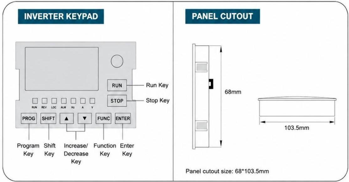
Main circuit: supply to input terminals, U/V/W to the motor, P+/PB for an optional braking resistor.
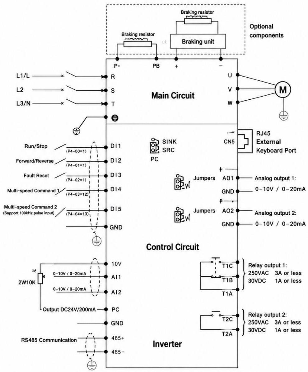
Control circuit: DI1–DI5, AI1/AI2 (0-10V/0-20mA), AO1/AO2, two relay outputs, RS485.


Installation Quick Guide
- Mount vertically on a non-flammable surface with ≥50mm airflow clearance.
- Wire input supply, then U/V/W to the motor (match motor voltage class).
- Connect P+/PB to a braking resistor for hard deceleration.
- Power on and run motor auto-tuning (P1-37) for best vector torque.
- Set P0/P1 minimum parameters and test at low speed first.
Datasheet & User Manual
Full VFD300 N manual — parameters, fault codes, wiring & dimensions (PDF).
Typical Applications
Related Products & Solutions
Get a Factory-Direct Quote
Tell us your motor power and application — we will recommend the exact model and ship within 3 days.