
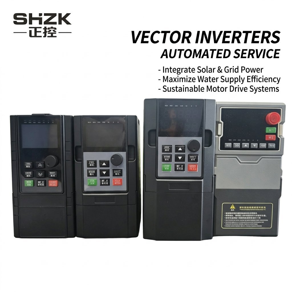
VFD 300 H2 Series – Single Phase 220V Input / Single Phase 220V Output
The VFD 300 H2 Series is a high-performance vector inverter designed for single-phase 220V input and single-phase 220V output applications. Ideal for small motor speed control with advanced SVPWM control technology.
Key Features
- Output Frequency: 0-600Hz
- Overload Capacity: 150% rated current for 1 minute, 180% for 3 seconds
- Control Method: Optimized SVPWM control
- Control Mode: Sensorless vector control with optimal low-frequency dead zone compensation
- Frequency Resolution: Digital 0.01Hz; Analog max frequency ×0.025%
- Built-in PID closed-loop control
- Multi-speed operation via built-in PLC or control terminals
- RS485 communication support
- 5 programmable digital inputs
- 2 analog inputs (0-20mA, 0-10V)
- 2 relay outputs
- Comprehensive protection: overcurrent, overvoltage, undervoltage, overheat, overload
Model Specifications
| Model | Rated Current | Dimensions (H×W×D mm) | IGBT |
|---|---|---|---|
| 300-0.75KWG-H2 | Input 3.5A / Output 3.5A | 165×98×128 | Single Tube |
| 300-1.5KWG-H2 | Input 8A / Output 6.8A | 165×98×128 | Single Tube |
| 300-2.2KWG-H2 | Input 10A / Output 10A | 165×98×128 | Single Tube |
| 300-3.0KWG-H2 | Input 13A / Output 13A | 187×100×137.5 | Single Tube |
Electrical Specifications
| Power Range | Input Voltage | Output Voltage | Output Frequency |
|---|---|---|---|
| 0.75kW – 3kW | Single Phase 220V 50/60Hz | Single Phase 0-220V | 0-600Hz |
Why Choose VFD300 H2 Series?
Direct single-phase 220V input and output — the simplest VFD solution for small motors, no phase conversion needed.
Match fan and pump speed to actual demand. Perfect for HVAC, small conveyors, and packaging equipment.
Smallest footprint in the VFD300 range. Wall-mount or DIN-rail options for tight control panels.
Most affordable VFD300 series. Ideal for OEM integration and small batch orders.
Quick Selection Guide — H2 Series
| Your Application | Recommended Model | Key Tip |
|---|---|---|
| Small Fan / Blower | Standard | Variable torque saves energy on continuous-run fans |
| Small Pump | Standard | Built-in PID for constant pressure water supply |
| Packaging / Textile Machine | Standard | Multi-speed for different production stages |
| OEM Integration | Custom Logo | MOQ 50 units for OEM branding |
Quick Specs at a Glance
| Input Voltage | 1PH AC 200V ~ 240V |
| Output Voltage | 1PH AC 0 ~ 240V |
| Power Range | 0.75kW – 3kW |
| Output Frequency | 0 – 600Hz |
| Control Mode | Sensorless Vector / V/F |
| Overload Capacity | 150%/60s |
| Best For | Single-phase motor speed control, OEM integration |
Complete Technical Specifications
| Parameter | Specification |
|---|---|
| Output Frequency | 0-600Hz |
| Carrier Frequency | 1.0-15.0kHz, automatically adjusts based on temperature and load |
| Control Method | Optimized space voltage vector SVPWM control |
| Control Mode | Sensorless vector control with optimal low-frequency dead zone compensation |
| V/F Control | Linear, multi-point, square root (selectable) |
| Frequency Resolution | Digital setting: 0.01Hz; Analog setting: max frequency × 0.025% |
| Starting Frequency | 0.0-10.0Hz |
| Starting Torque | 0.5Hz / 180% (Sensorless Vector Control); 1Hz / 180% (V/F) |
| Torque Boost | Automatic torque boost; Manual torque boost 0.1%-30.0% |
| Speed Control Accuracy | ±0.5% of maximum speed (Sensorless Vector Control) |
| Speed Adjustment Range | 1:100 (Sensorless Vector Control) |
| Overload Capacity (G-type) | 150% rated current for 1 minute, 180% rated current for 3 seconds |
| Overload Capacity (P-type) | 120% rated current for 60 seconds, 150% rated current for 10 seconds |
| Acceleration/Deceleration | Linear or S-curve, 4 sets of accel/decel time (0.1-3600s) |
| DC Braking | DC braking at start and stop |
| Jog Operation | Jog frequency: 0.0Hz to max frequency; Jog accel/decel time: 0.1-3600s |
| Built-in PID | Closed-loop control for pressure, flow, temperature regulation |
| Multi-speed Operation | Up to 16-speed via built-in PLC or control terminals |
| Run Command Channel | Control panel, control terminals, RS485 communication |
| Frequency Setting | Digital keypad, analog input (AI1/AI2), RS485, multi-speed, simple PLC, PID |
| Digital Input | 5 programmable digital inputs (DI1-DI5), DI5 supports 20kHz high-speed pulse input |
| Analog Input | 2 channels (AI1, AI2): 0-20mA / 0-10V selectable |
| Analog Output | 2 channels (AO1, AO2): 0-20mA or 0-10V selectable |
| Relay Output | 2 relays: NO/NC, rated AC250V 3A / DC30V 1A |
| Communication | RS485 Modbus RTU (standard) |
| Protection | Overcurrent, overvoltage, undervoltage, overheat, overload, input/output phase loss, motor overheat (PTC), ground fault |
| Display | LED display showing set frequency, output frequency, output voltage, output current, etc. |
| Operating Temperature | -10°C to +50°C (derating above 40°C) |
| Storage Temperature | -20°C to +60°C |
| Humidity | ≤95% RH, non-condensing |
| Altitude | ≤1000m (derate 1% per 100m above 1000m) |
| Protection Degree | IP20 (standard); IP54 available on request |
| Installation | Wall mount or flange mount |
| Cooling | Forced air cooling |
| Quality Assurance | 100% full-load aging test before shipment |
Model Naming Convention
SHZK VFD300 models follow a standardized naming system for easy identification:
XXX – 055 G B – T4 – L
| Position | Code | Description |
|---|---|---|
| Series | 300 | VFD300 Series |
| Power Rating | 007 | 0.75 kW |
| 015 | 1.5 kW | |
| 055 | 5.5 kW | |
| 720 | 72 kW | |
| 800 | 80 kW | |
| Motor Type | G | General purpose (standard industrial) |
| P | Fan & Pump type (light-duty, 120% overload) | |
| PV | Solar/PV dedicated (MPPT/CVT solar tracking) | |
| Braking Unit | B | With built-in braking unit |
| (blank) | Without braking unit | |
| Voltage Class | T4 | 3PH AC 380-480V Input / 3PH 0-480V Output |
| T2 | 3PH AC 200-240V Input / 3PH 0-240V Output | |
| S2 | 1PH AC 200-240V Input / 3PH 0-240V Output | |
| S3 | 1PH AC 200-240V Input / 3PH 0-400V Output | |
| H2 | 1PH AC 200-240V Input / 1PH 0-240V Output | |
| Reactor Option | (blank) | No reactor |
| -L | With AC output reactor | |
| -T | With DC reactor |
Available Configurations
| Configuration | Model Suffix | Best For |
|---|---|---|
| General Industrial | G | Conveyors, CNC, mixers, general machinery |
| Fan & Pump (Energy Saving) | P | Centrifugal pumps, HVAC fans, blowers (lower overload, optimized for variable torque loads) |
| Solar/PV Dedicated | PV | Solar water pumping, agricultural irrigation, off-grid water supply (MPPT + CVT dual-mode solar tracking) |
Optional Accessories
- Braking Unit (B): Built-in braking resistor for applications requiring fast deceleration (cranes, hoists, elevators)
- AC Output Reactor (-L): Recommended for long motor cable runs (>50m) or multiple motors on one VFD
- DC Reactor (-T): Improves power factor and reduces harmonic distortion for large installations
- Communication Cards: Profibus-DP and Profinet modules available on request for SCADA integration
Applications
CNC machines, small conveyors, packaging equipment, textile machinery, and other single-phase motor control applications.
OEM & ODM available. Contact us for pricing and technical support.
Control Circuit Wiring Diagrams
The following diagrams show the control circuit terminal layout and wiring for each main board type used in the 300 Series.
Main Circuit Terminal Layout
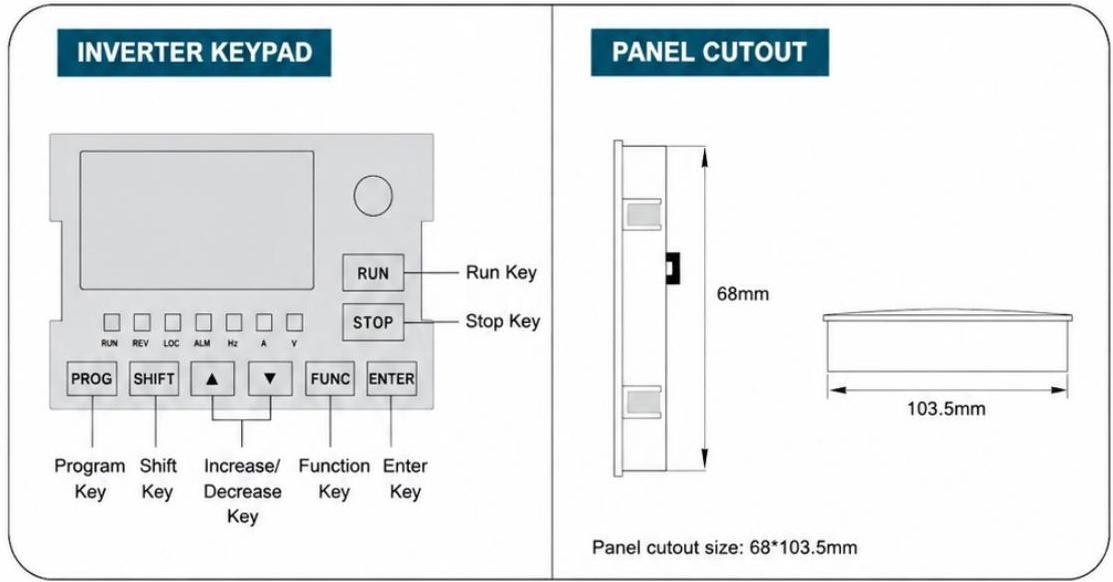
Main Circuit Terminal Layout (R/L1, S/L2, T — PP, PB — U, V, W — G, E)
A-Type Main Board Wiring Diagram
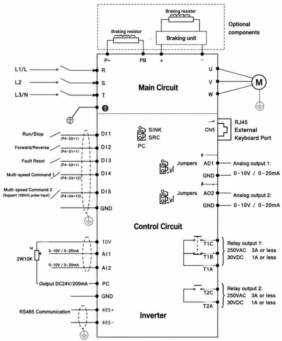
Wiring Notes
- Analog voltage signals require shielded cables; wiring distance should not exceed 20m.
- In severe interference environments, equip analog signal source side with filter capacitor or ferrite core.
- Terminal assignments may vary by model — refer to actual product labeling.