
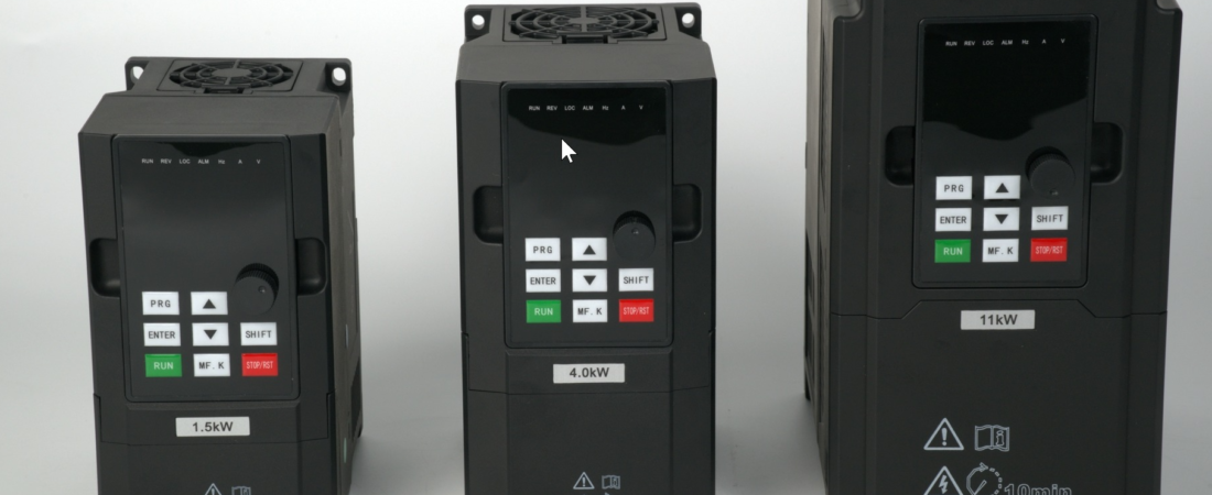
Getting the vfd mounting dimensions and vfd clearance right before you drill a single hole saves you a weekend of rework. On our assembly line at SHZK, I watch integrators make the same mistakes repeatedly — drives bolted flush against a back panel, zero airflow above the heatsink fins, cables pinched against the chassis. This guide pulls the installation rules directly from our 300N series manual (Chapter 1.5) and adds the practical notes I have picked up watching these units come off the test bench every day.
SHZK 300N Series at a Glance
The 300N series covers 0.75 kW through 800 kW across multiple voltage classes. Before you measure anything, confirm your model code. A quick example from our nameplate spec:
| Model Code | Meaning |
|---|---|
| 300N | Product series |
| 055 | 55 kW power rating |
| G | General-purpose type |
| B | Braking unit included |
| T4 | 3PH 380–480 V input / 0–480 V output |
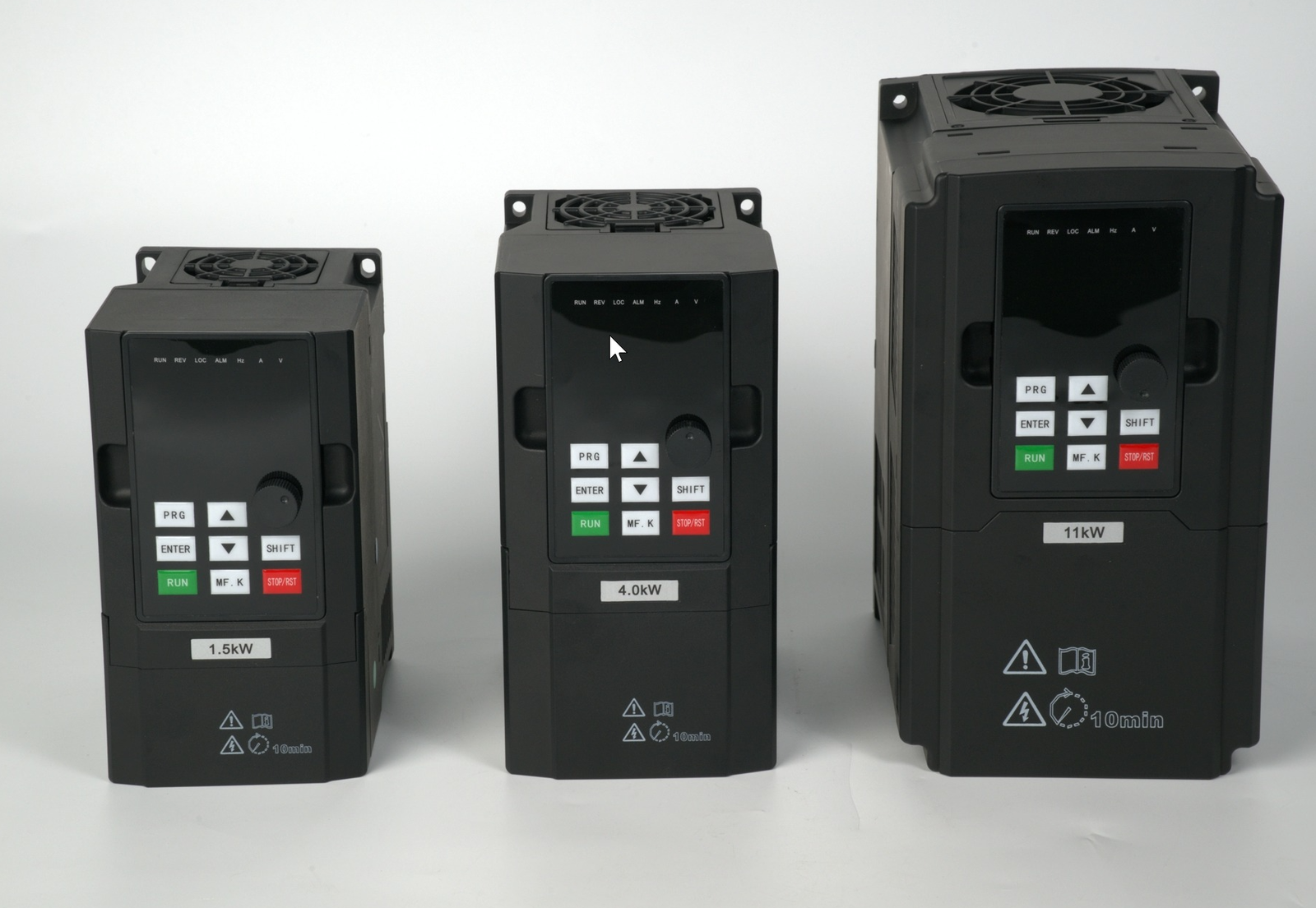
Voltage classes available: T4 (3PH 380–480 V), T2 (3PH 200–240 V), S2 (1PH 200–240 V input / 3PH 0–240 V output), H2 (1PH 200–240 V in/out), and S3 (1PH 200–240 V input / 3PH 0–400 V output). Each frame size has its own mounting hole pattern — always confirm against the drawing in Section 1.5.1 Installation Hole Dimensions of your specific unit’s manual before cutting any panel.
Wall-Mount vs. In-Cabinet: Which Applies to You
Two installation scenarios show up on our support line daily. The rules differ.
Open Wall Mount
- Mount the drive vertically on a flat, non-flammable surface.
- Maintain the minimum clearance specified in Chapter 1.5.1 on all sides — top, bottom, left, and right. The heatsink exhausts upward; blocking the top kills the unit faster than any electrical fault.
- Use the mounting hole pattern from the exterior design diagram. Do not eyeball it.
- If the ambient environment carries conductive dust or corrosive gas, wall-mount is the wrong choice — move to a sealed cabinet with filtered intake.
In-Cabinet (Enclosed) Installation
This is where most thermal problems start. The drive sits inside a metal enclosure, and the cabinet designer treats it like any other component. It is not.
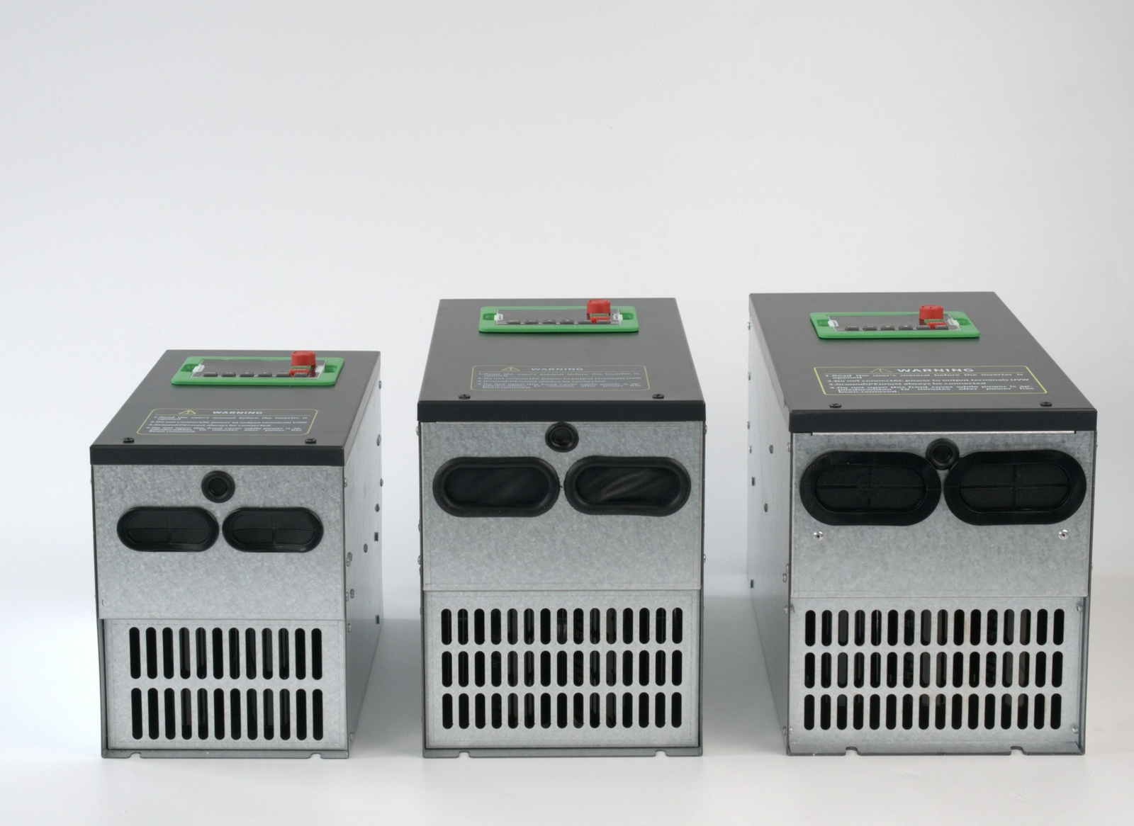
- Top clearance: The hottest air exits here. Give it room to rise and escape through a cabinet exhaust vent or fan.
- Bottom clearance: Cooler air enters from below. If the cabinet floor is solid with no intake, you are starving the drive.
- Side clearance: Needed for airflow across the heatsink fins and for physical access during maintenance.
- For detailed hole-by-hole numbers, refer to Section 1.5.1 of the manual matched to your frame size.
Thermal Reality Check from the Test Floor
Every 300N unit we ship passes a full-load burn-in on the test bench. I have seen the thermal camera images. A drive with correct clearance runs its IGBT module at roughly 15–25 °C above ambient. The same drive stuffed into a cabinet with 20 mm top clearance? The module temperature climbs 40 °C higher. That cuts capacitor life in half. The fundamentals of VFD thermal design are well documented, but the execution always comes down to millimeters of free air space.
Our internal heatsink and power module layout is designed around forced convection. Blocking airflow paths defeats the engineering.

What Happens When Clearance Is Wrong
Derating. Every manufacturer publishes a temperature derating curve. Above a certain ambient threshold — typically 40 °C for standard units — you must reduce the output current. Ignore this and you trip on over-temperature. Our fault code reference lists every thermal alarm and what it means.
Cabinet Cooling Design: Practical Rules
Bottom-to-top. Cool air enters low, warm air exits high. Never reverse this.
Cabinet intake filters clog. Check them monthly in dusty environments. A clogged filter is the same as zero clearance.
Stacking drives vertically without airflow separation between units is a common mistake. Each drive needs its own clearance envelope.
For sealed IP54+ cabinets, use a forced ventilation kit or air-to-air heat exchanger. Calculate the total heat dissipation of all drives inside before sizing the cooling system.
Quick Parameter Reference — 300N Series Electrical Specs
These values come directly from the 300N nameplate and specification data. Use them to size your input wiring, breaker panel, and cabinet space.
| Model Example | Power | Input Voltage | Input Current | Output Voltage | Output Current | Frequency Range |
|---|---|---|---|---|---|---|
| 300N-055GB-T4 | 55 kW | 3PH 380–480 V | 106 A | 3PH 0–480 V | 112 A | 0–500 Hz |
| 300N-0075-T2 | 0.75 kW | 3PH 200–240 V | — | 3PH 0–240 V | — | 0–500 Hz |
| 300N-800-T4 | 800 kW | 3PH 380–480 V | — | 3PH 0–480 V | — | 0–500 Hz |
Note: Full current ratings for every frame size are listed in Section 1.4 of the manual. Always match your motor nameplate current against the VFD output current rating — not just the kW figure.
Mounting Checklist Before You Power Up
Common Mistakes I See on Site
1. Mounting the drive upside down. It happens. The heatsink fins need to be vertical so convection carries heat upward. Horizontal mounting reverses the thermal path.
2. Ignoring the external keyboard clearance. Section 1.5.2 of the manual covers the external dimensions of the optional external keypad. If you are using one, it needs its own space — do not trap it against the cabinet door with zero gap.
3. Assuming all VFDs share the same footprint. They do not. Even within the 300N family, a 1.5 kW unit and an 11 kW unit have completely different wiring terminal layouts and physical envelopes. Always reference the drawing for your specific model.
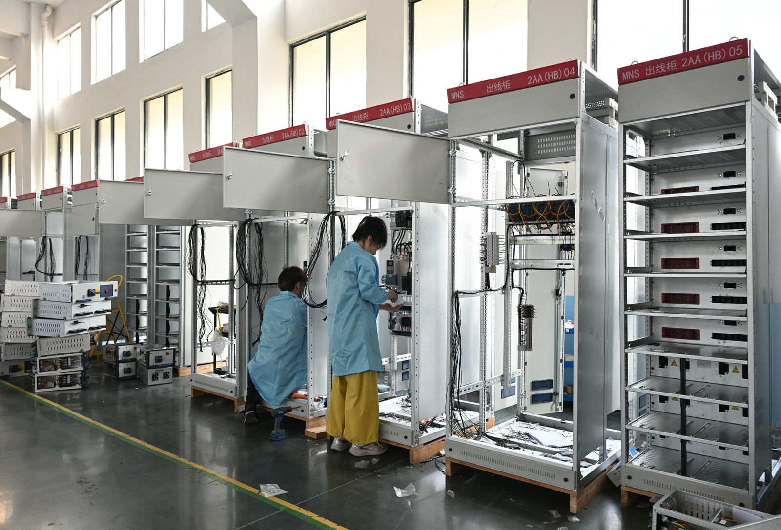
Our MNS cabinet assembly workshop builds complete drive systems with proper thermal management baked in. If you need a turnkey solution rather than field-mounting individual drives, we can spec the entire enclosure for you — including filtered ventilation, busbar layout, and IP rating.
When Clearance Alone Is Not Enough
Some environments defeat any amount of passive clearance. Foundries, textile mills, chemical plants with corrosive atmosphere — the air itself is the enemy. In these cases:
- Use a sealed NEMA 12 or IP54 cabinet with a closed-loop air-to-air heat exchanger.
- Consider conformal-coated control boards — our 300N units can be ordered with coated PCBs for harsh environments.
- Positive pressure cabinets with filtered air supply keep dust and moisture out entirely.
The Modbus communication standard lets you monitor drive temperature in real time through parameter registers. Set up an alarm threshold before the drive reaches its thermal limit. Our monitoring parameters guide shows exactly which registers to poll.
Related Technical Guides
→ VFD Fault Codes: Complete Alarm Reference
→ VFD Overcurrent Fault: Diagnosis & Fixes
→ VFD Parameter Setup: First Commissioning Steps
→ VFD Monitoring Parameters: What to Watch
→ Browse All Technical Guides
Need help selecting the right VFD?
Contact our engineering team for free application consultation — from mounting layout to parameter configuration.
Email: mail@shzkvfd.com
WhatsApp: +86 13757750205