
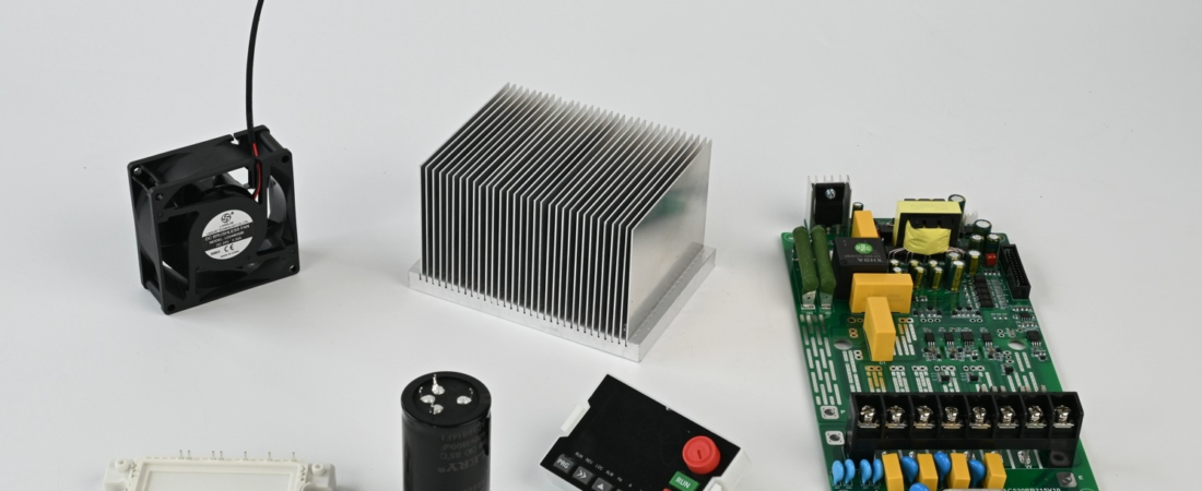
Running a variable frequency drive past its consumable life is the single most common reason we see field failures that could have been avoided on the test floor. A disciplined vfd maintenance routine — focused on the cooling fan, the DC bus capacitors, and the buffer (pre-charge) resistor — keeps the 300N series running well beyond its warranty window. This article pulls directly from our production and test-line experience with the SHZK 300N lineup, rated from 0.75 kW up to 800 kW across T4 (380–480 V), T2 (200–240 V), and single-phase input variants (S2, H2, S3).
Why the Big Three Components Drive Your VFD Service Schedule
Inside every 300N drive, three parts age on a predictable curve while the IGBTs and control board stay healthy for decades. The cooling fan wears its bearings, the electrolytic capacitors dry out, and the buffer resistor absorbs inrush stress every time the drive powers up. Replace them on time and the drive keeps performing. Ignore them and Chapter 5 of the manual — Fault Diagnosis and Countermeasures — starts reading like a checklist of things about to fail.
We see this pattern every week on our variable-frequency drive test benches. A 55 kW unit (model 300N-055GB-T4, input 3PH 380–480 V / 106 A, output 112 A) comes back from a harsh environment with a fan bearing noise at 18 months. The drive itself is fine. The capacitors are fine. Only the fan failed — and only because nobody scheduled the swap.


Cooling Fan Replacement
The fan on a 300N drive moves air across the heatsink that carries the IGBT modules. Once bearing wear raises vibration or drops airflow by more than 20 %, the internal temperature climbs and the drive begins to derate. On our assembly line we run every unit through a thermal soak; a fan that is past its service life shows up as an elevated heatsink temperature within minutes.
Replacement interval
- Standard industrial environment (clean, ≤40 °C ambient): replace every 2–3 years or at the first sign of bearing noise.
- Harsh environment (textile, ceramic, high dust, >40 °C): replace every 12–18 months.
- Continuous heavy load (fan/pump duty at 90 %+ of rated current): inspect quarterly, replace at 24 months.
Our rear-ventilation design on the 300N makes the fan accessible without removing the power stage. Always disconnect mains, wait for the DC bus to discharge, and verify <25 V DC on the bus before touching anything.
DC Bus Capacitor Replacement
Electrolytic capacitors on the DC bus are the single most temperature-sensitive component in any VFD. Their internal electrolyte evaporates over time, and the rate of evaporation roughly doubles for every 10 °C rise in operating temperature. A drive that runs hot will kill its capacitors in half the expected life.
Replacement interval
- Standard duty, ambient ≤40 °C: 5–7 years.
- Hot or high-ripple duty (frequent starts, heavy braking on models without the
Bbraking unit option): 3–5 years. - Signs of end-of-life: visible vent bulging, electrolyte leakage on the PCB, ESR measured above twice the datasheet value, or a recurring overvoltage fault at deceleration that cannot be resolved by adjusting parameters.
On a 15 kW power stage like the one we build here, the bus capacitor bank is the largest single component. Capacitor replacement is the most labour-intensive item on the vfd service schedule, and it is the one that pays back the most in avoided downtime.


Buffer (Pre-Charge) Resistor Replacement
The buffer resistor limits inrush current when the drive is first energised, before the main contactor or relay closes across the DC bus. Every power-on cycle dumps a pulse of energy into it. On a machine that is switched off nightly, that is roughly 250–300 thermal cycles per year; on a process line that stays powered, only a few dozen.
Replacement interval
- Continuous-power installations: inspect at 5 years, replace only if resistance has drifted or the element shows heat discolouration.
- Frequent power cycling (daily start/stop): inspect at 3 years, plan replacement at 5 years.
- Failure symptoms: drive trips on DC bus undervoltage at power-up, visible cracking or burn marks on the resistor body, or an open-circuit reading on an ohmmeter.
For drives equipped with the B option (integrated braking unit, e.g. 300N-055GB-T4), the braking resistor is a separate external component and follows its own duty cycle — it is not the same part as the internal buffer resistor.
Quick Parameter & Model Reference for the 300N Service Schedule
The table below pulls model codes and ratings straight from the 300N nameplate convention. Use it to confirm which voltage class and braking option your unit carries before ordering spares.
| Model code | Power | Voltage class | Braking unit | Typical fan interval |
|---|---|---|---|---|
300N-007G-T4 |
0.75 kW | T4: 380–480 V | No | 2–3 yr |
300N-055G-T4 |
5.5 kW | T4: 380–480 V | No | 2–3 yr |
300N-055GB-T4 |
5.5 kW | T4: 380–480 V | Yes (B) |
2–3 yr |
300N-075G-T4 |
7.5 kW | T4: 380–480 V | No | 2–3 yr |
300N-xxxG-T2 |
0.75–800 kW | T2: 200–240 V | per option | 2–3 yr |
300N-xxxG-S2 |
single-phase in | S2: 1PH 200–240 V | per option | 2–3 yr |
For fault codes that often point back to these three consumables — overcurrent, overvoltage, and DC bus undervoltage — see our dedicated guides on overcurrent faults and overvoltage faults. Proper wiring practices, covered in the VFD wiring guide, also extend capacitor life by keeping harmonic ripple low.
Building a Realistic VFD Service Schedule on Your Site
Put the three consumables on a calendar, not on a breakdown. A workable schedule looks like this:
Quarterly
Visual inspection of fan airflow, listen for bearing noise, check resistor for heat marks.
Annually
Measure DC bus ripple, verify capacitor ESR if accessible, clean heatsink fins.
Every 2–3 years
Replace cooling fan regardless of apparent condition.
Every 5–7 years
Replace DC bus capacitors and inspect buffer resistor; re-torque power terminals.
Document every swap with the drive serial number. The nameplate format — for example 300N-055GB-T4 with input 3PH 380–480 V / 106 A, output 112 A, 55 kW — gives you everything you need to order the correct fan, capacitor bank, and resistor for that exact frame size. For deeper parameter work once the drive is back in service, our VFD parameter setup guide walks through the function parameter table from Chapter 4 of the manual.
For installations that rely on Modbus RTU supervision, you can also schedule maintenance from the monitoring parameters page, using live readings of DC bus voltage, fan speed feedback, and heatsink temperature to move from calendar-based to condition-based maintenance.
Related Technical Guides
Need help selecting the right VFD?
Contact our engineering team at mail@shzkvfd.com or WhatsApp +86 13757750205 for free application consultation.