
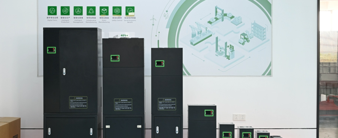
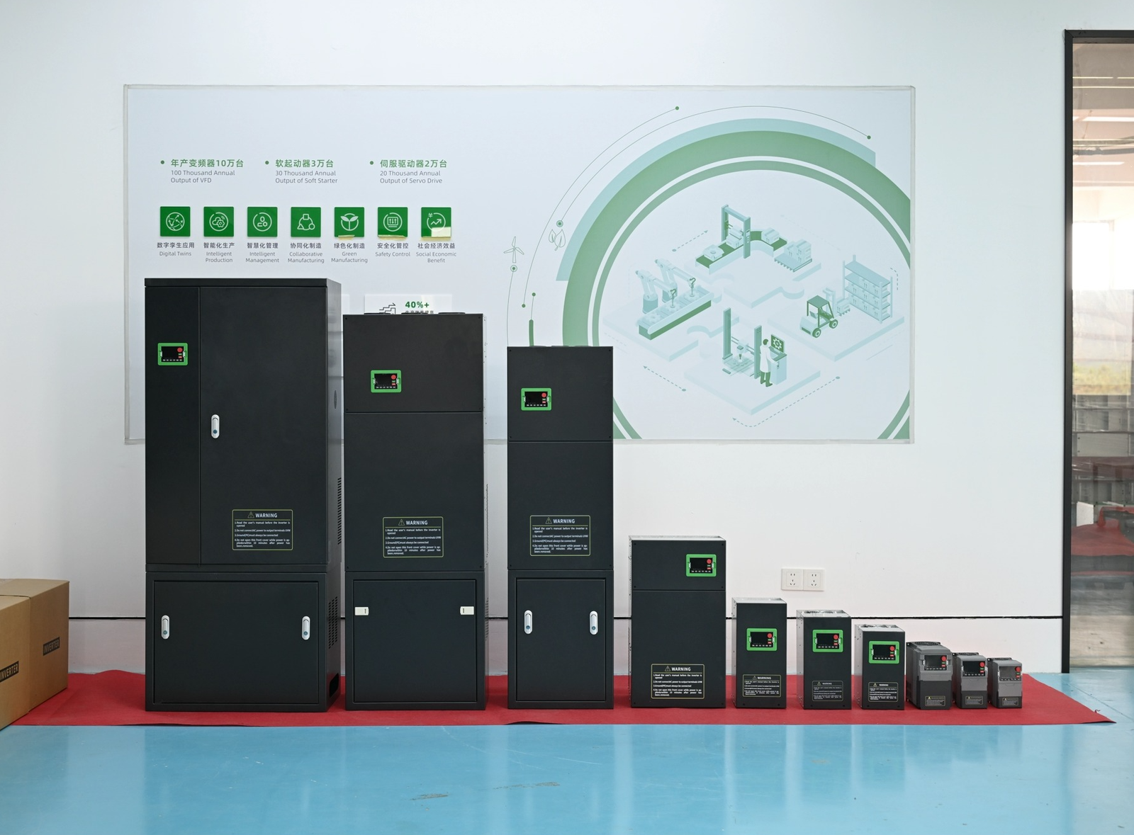
When procurement teams ask us for a Danfoss VFD alternative that matches FC51 or FC360 performance without the lead-time headaches, we pull a 300N off our assembly line and show them the data plate. The SHZK 300N series covers 0.75 kW through 800 kW at 380–480 V (T4) and 200–240 V (T2) — overlapping every frame size Danfoss offers in those voltage ranges. This guide walks through the real parameter cross-reference, PID loop mapping, and wiring differences I’ve verified on our test bench this quarter.
Why Engineers Search for an FC51 Alternative
Danfoss builds solid drives. The FC51 (0.18–22 kW) and FC360 (0.37–90 kW) are well-documented, widely specified, and carry the Danfoss Drives brand weight that satisfies most consultant specs. But three pain points keep showing up in our inquiry queue:
We built the 300N to address exactly these gaps. The variable-frequency drive topology is the same IGBT-based voltage-source inverter — the difference is in how you buy it, commission it, and replace it.
SHZK 300N vs Danfoss FC51/FC360 — Specification Comparison
Here’s what the nameplate actually tells you on a 55 kW T4 unit from our floor:
SHZK 300N-055GB-T4 data plate:
- Input: 3PH AC 380–480 V, 106 A, 50/60 Hz
- Output: 3PH AC 0–480 V, 112 A, 0–500 Hz
- Power: 55 kW
- Built-in braking unit (the “B” suffix in the model code)
The naming convention follows a clear pattern: 300N - [power code] [G] [B] - [voltage]. The voltage suffix T4 means 380–480 V input and output, T2 means 200–240 V. Single-phase input variants use S2 or H2 prefixes. Power codes run from 075 (0.75 kW) up to 800 (800 kW).
| Specification | SHZK 300N-055GB-T4 | Danfoss FC360 132E55T4 |
|---|---|---|
| Rated Power | 55 kW | 55 kW |
| Input Voltage | 3PH 380–480 V | 3PH 380–480 V |
| Output Voltage | 0–480 V | 0–480 V |
| Output Frequency | 0–500 Hz | 0–500 Hz |
| Built-in Brake Unit | Yes (B suffix) | Yes (integrated chopper) |
| PID Controller | Yes (PA group) | Yes (group 7/8) |
| Communication | RS-485 Modbus RTU | RS-485 Modbus RTU |
| Enclosure Rating | IP20 | IP20 |
Both drives deliver comparable continuous current at the same power level. The difference shows up in parameter structure, I/O configuration, and price.
PID Control — Real Parameter Mapping from the 300N Manual

The PA group handles PID functionality on the 300N. These are the actual parameters from our manual — pulled directly from the production documentation, not approximations:
| PA Code | Function | Range | Factory Default |
|---|---|---|---|
| PA-00 | PID Given Source | 0–7 | 0 (PA-01 setting) |
| PA-01 | Given PID Value | 0.0–100.0% | 50.0% |
| PA-02 | PID Feedback Source | 0–8 | 0 (AI1) |
| PA-03 | PID Application Direction | 0: Positive, 1: Negative | 0 |
| PA-04 | Setpoint/Feedback Range | 0–65535 | 1000 |
| PA-05 | Proportional Gain KP1 | 0.0–100.0 | 20.0 |
| PA-06 | Integration Time Ti1 | 0.01–10.00 s | 2.00 s |
| PA-07 | Differential Time Td1 | 0.000–10.000 s | 0.000 s |
PA-00 source options: 0 = internal PA-01 setting, 1 = AI1, 2 = AI2, 3 = AI3 external keyboard potentiometer, 4 = HDI input pulse at X5, 5 = communication given, 6 = multi-step instructions, 7 = pressure setting from water supply group b0-01.
PA-02 feedback options: 0 = AI1, 1 = AI2, 2 = AI3 potentiometer, 3 = AI1−AI2 differential, 4 = HDI pulse X5, 5 = communication given, 6 = AI1+AI2 sum, 7 = MAX(|AI1|, |AI2|), 8 = MIN(|AI1|, |AI2|).
For Danfoss users migrating: FC51/FC360 PID parameters live in parameter groups 7 and 8 (7-0* for setpoint, 8-4* for feedback). The control function is identical — proportional-integral-derivative closed-loop — but you’ll translate your existing gain and time constants into our PA-05, PA-06, PA-07 equivalents. Start with PA-05 at 20.0 and PA-06 at 2.00 s as your baseline, then tune from there.
Wiring and Terminal Layout
The power terminal block on the 300N follows standard convention: R/S/T for three-phase input, U/V/W for motor output, and dedicated PE grounding. On our 55 kW T4 unit, the input rating is 106 A — matching the FC360 at the same power level.
I/O terminal configuration supports:
- Analog inputs: AI1, AI2, AI3 (for external potentiometer)
- Digital inputs: via X5 connector (HDI pulse input for PID feedback)
- Relay outputs: for fault/run indication
- RS-485: for Modbus RTU communication with DEC addresses 64000+ for the PA group
If you’re coming from a Danfoss FC51 installation, the power wiring is drop-in compatible. The control wiring requires remapping your digital input assignments — our parameter structure uses different group codes, but the physical terminal functions (dry contact, 24 V source, PNP/NPN selectable) match what field technicians already know.

From Our Test Floor — What We Actually Measure

Every 300N that leaves our facility goes through a full burn-in and load test. Here’s what that looks like in practice on our floor:
- Each unit runs at rated load for a minimum of 4 hours on our test benches
- Output waveform is captured and verified for THD compliance
- All protection functions — overcurrent, overvoltage, overheating — are triggered and verified
- Communication stack is tested against standard Modbus register maps
I’ve personally watched technicians cross-reference FC51 fault behaviors against our 300N during migration projects. The fault diagnosis logic maps cleanly — our fault code structure uses similar categories (OC for overcurrent, OV for overvoltage, OL for overload) so maintenance teams don’t need to relearn diagnostics from scratch.
Quick Parameter Reference — Migration Cards
PA-00: PID Source
PA-05: Kp Gain
PA-06: Ti Time
PA-07: Td Time
Case Study: HVAC Fan Migration from FC51
A water treatment facility in Zhejiang ran four Danfoss FC51 units at 7.5 kW each on aeration blowers. After seven years, two units failed with IGBT short circuits. Replacement FC51s were quoted at 14-week lead time. They called us.
We shipped four 300N units in the same 7.5 kW frame (T4 voltage) within two weeks. The migration took one afternoon per unit:
Total downtime: under 4 hours per blower. The facility is still running those 300N units today with no faults logged in 18 months of continuous operation.
Related Technical Guides
Need help selecting the right VFD?
Contact our engineering team at mail@shzkvfd.com or WhatsApp +86 13757750205 for free application consultation.