

Overcoming the Complexities of VFD Multi-Speed Control in Industrial Automation
In modern industrial automation, EPC contractors and system integrators frequently encounter machinery that requires precise, multi-step speed adjustments without the overhead of complex programming. Relying on analog signals or extensive PLC logic for these tasks can inflate project costs, increase panel space requirements, and introduce unnecessary points of failure. This is where mastering VFD multi-speed control becomes a critical competency for engineering teams. When configuring a drive for applications like conveyor sorting, centrifugal separators, or machine tool spindle drives, engineers often struggle with the initial setup of the VFD digital input terminals. Misconfiguring the logic levels, failing to properly map the DI terminal VFD functions, or misunderstanding the binary selection logic can lead to erratic motor behavior, unexpected fault trips, and costly commissioning delays. Wholesale buyers and distributors also face the challenge of supporting end-users who lack the technical depth to configure these parameters correctly in the field. By standardizing the multi-speed setup process, you can drastically reduce technical support tickets, accelerate commissioning times, and ensure seamless integration into diverse industrial environments. Understanding how to effectively utilize discrete digital inputs for speed selection not only simplifies the overall control architecture but also enhances the reliability and maintainability of the automation system.

Configuring Digital Inputs for Multi-Speed Operation
To achieve reliable VFD speed presets, engineers must correctly map the physical digital inputs to the internal drive parameters. In Lakinele drives, such as the robust 300N T4 Series, the control board features up to six programmable digital inputs (DI1 through DI6) designed for flexible control architectures. The foundational step is defining the primary control commands. Typically, DI1 is assigned to Run/Stop (Function Code 1), and DI2 is set to Forward/Reverse (Function Code 2). A Fault Reset function is often mapped to DI3 (Function Code 8) to allow operators to clear alarms via an external pushbutton, ensuring rapid recovery from transient faults.
For multi-speed operation, the drive utilizes a binary coding system to select predefined frequencies. By assigning Multi-speed Command 1 (Function Code 12) to DI4, Multi-speed Command 2 (Function Code 13) to DI5, and Multi-speed Command 3 (Function Code 14) to DI6, you can select up to eight distinct speed levels. These parameters are configured in the input terminal group, specifically P4-00 through P4-05. For instance, setting P4-03 to 12, P4-04 to 13, and P4-05 to 14 activates the multi-speed selection logic. The actual speed values are then programmed into the multi-speed parameter group (e.g., P9-00 to P9-07), representing 0.00% to 100.00% of the maximum frequency. If all three inputs are open, the drive defaults to the base speed programmed in P9-00.
Crucially, the electrical interface must match the control system’s logic. Lakinele VFDs support both NPN (sink) and PNP (source) wiring configurations. For an NPN setup, common in many Asian and European PLCs, the digital inputs are triggered by connecting them to the common ground (COM/-). Conversely, a PNP setup, preferred in North American systems, triggers the inputs by connecting them to the +24V supply. Properly configuring the hardware jumper or parameter setting to match the sink/source mode prevents false triggering and ensures signal integrity. For single-phase applications requiring similar multi-speed capabilities, the S2 Series offers the exact same parameter structure, ensuring a unified programming experience across your product portfolio.
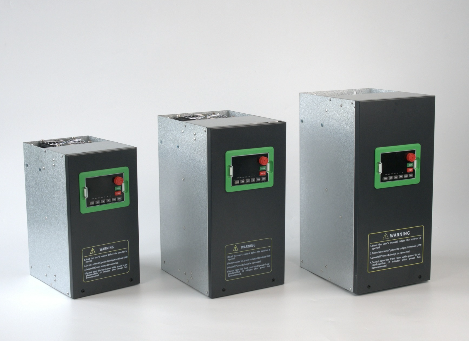
Digital Input Terminal Specifications and Parameter Mapping
| Terminal | Default Function | Function Code | Multi-Speed Binary Weight | Electrical Characteristic |
|---|---|---|---|---|
| DI1 | Run/Stop | 1 | N/A | Sink/Source Selectable, 24VDC max, 7mA typical |
| DI2 | Forward/Reverse | 2 | N/A | Sink/Source Selectable, 24VDC max, 7mA typical |
| DI3 | Fault Reset | 8 | N/A | Sink/Source Selectable, 24VDC max, 7mA typical |
| DI4 | Multi-speed Command 1 | 12 | Bit 0 (Activates Speed 1, 3, 5, 7) | Sink/Source Selectable, 24VDC max, 7mA typical |
| DI5 | Multi-speed Command 2 | 13 | Bit 1 (Activates Speed 2, 3, 6, 7) | Sink/Source Selectable, 24VDC max, 7mA typical |
| DI6 | Multi-speed Command 3 | 14 | Bit 2 (Activates Speed 4, 5, 6, 7) | Sink/Source Selectable, 24VDC max, 7mA typical |
Real-World B2B Applications for Multi-Speed VFDs
- Automated Conveyor Sorting Systems: In logistics and packaging, conveyors often need to run at a creep speed for precise item placement, a medium speed for standard transport, and a high speed for clearing jams. Using three digital inputs, operators can instantly toggle between these VFD speed presets via a physical rotary switch, eliminating the need for complex HMI programming on the line and reducing mechanical wear during start-stop cycles.
- Machine Tool Spindle Drives: CNC lathes and milling machines require different spindle speeds for roughing, finishing, and tapping operations. By wiring external selector switches to the DI terminal VFD inputs, machinists can seamlessly transition between predefined RPM ranges. This ensures optimal tool life and surface finish quality without interrupting the machining cycle or requiring manual parameter adjustments on the keypad.
- Industrial Washing and Mixing Equipment: Batch processing equipment often follows a specific recipe of slow agitation, high-speed mixing, and medium-speed rinsing. Multi-speed control allows the drive to execute these phases based on simple dry-contact closures from a PLC or timer relay. This provides robust and reliable operation in harsh, washdown environments where analog signals might be susceptible to electrical noise.
Frequently Asked Questions
Can I use the same multi-speed configuration across different Lakinele VFD series?
Yes, the parameter structure for digital input configuration, specifically P4-00 through P4-05, is standardized across our product lines. Whether you are deploying the three-phase 300N T4 Series or the single-phase H2 Series, the logic for mapping multi-speed commands remains identical, simplifying training and maintenance for your technical teams.
How do I switch between NPN and PNP wiring modes for the digital inputs?
Lakinele VFDs feature a hardware jumper on the control board, typically labeled SINK/SOURCE, which must be physically moved to match your control voltage wiring. Additionally, ensure that the corresponding input logic parameter is set correctly to match the physical jumper position to prevent input signal errors and ensure safe operation.
What happens if multiple multi-speed digital inputs are triggered simultaneously?
The drive interprets simultaneous inputs as a binary code to select the corresponding speed preset. For example, if Multi-speed 1 (DI4) and Multi-speed 2 (DI5) are both active, the drive reads the binary value and executes the speed programmed in the third multi-speed parameter slot, allowing for seamless transitions between up to eight distinct speeds.
Do I need a PLC to utilize the multi-speed digital input features?
No, a PLC is not required to take advantage of these features. You can easily use manual selector switches, rotary cams, or simple relay logic to close the dry contacts on the digital input terminals, making it a highly cost-effective solution for standalone machines or simple automation upgrades.
What is the maximum voltage and current rating for the digital input terminals?
The digital input terminals are designed to accept a maximum voltage of 24VDC and typically draw a current of around 7mA per channel. It is crucial to ensure that any external control circuitry does not exceed this 24VDC limit, as overvoltage can permanently damage the internal input optocouplers.
Optimize Your Automation Projects with Lakinele VFDs
Streamlining your industrial automation projects starts with selecting the right drive and configuring it flawlessly. At Lakinele, we provide comprehensive technical support to help distributors, EPC contractors, and importers master VFD multi-speed control and other advanced functionalities. Our extensive catalog includes the heavy-duty 300N T4 Series for demanding three-phase applications, the versatile S3 Series for single-to-three-phase 380V conversions, and the compact H2 Series for lighter single-phase duties. Explore our complete product range to find the perfect match for your specific application requirements. For detailed wiring diagrams, parameter manuals, and application notes, reach out to our engineering team today to ensure your next project is a success.
Get Multi-Speed Configuration Guide
Contact Sales Team