
Overcoming CNC Machining Challenges with the Right Variable Frequency Drive
In the high-stakes world of computer numerical control manufacturing, even minor inconsistencies in motor speed can lead to catastrophic tool breakage, poor surface finishes, and costly material waste. For B2B buyers, wholesale distributors, and EPC contractors sourcing industrial automation components, selecting the right CNC VFD is not just about matching basic voltage and current ratings; it is about ensuring flawless precision control under highly dynamic load conditions. When a spindle drive fails to maintain consistent torque at low speeds or exhibits excessive vibration at high RPMs, the entire production line suffers from reduced throughput and compromised quality.
Many international importers face the frustrating reality of generic inverters that lack the specialized algorithms required for high-frequency spindle motors, resulting in overheating, premature component failure, and reduced tool life. The core challenge lies in finding a reliable CNC machine inverter that seamlessly integrates with complex CNC controllers, offers rapid acceleration and deceleration without tripping, and delivers stable power output in electrically noisy factory environments. This comprehensive guide will navigate the critical selection criteria and installation best practices to ensure your CNC applications achieve maximum uptime, superior machining accuracy, and long-term reliability for your end-users.
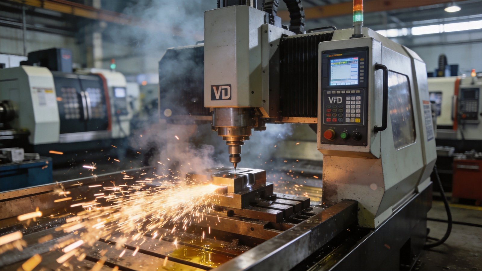
Selection Criteria and Installation Best Practices for CNC Spindle Drives
Selecting the optimal drive for CNC applications requires a deep understanding of both the motor characteristics and the specific machining process. The most critical parameter to evaluate is the carrier frequency. Standard industrial drives typically operate at 2kHz to 4kHz, but CNC spindle motors often require carrier frequencies up to 15kHz or even 20kHz to minimize acoustic noise and reduce motor heating. Furthermore, the drive must support advanced sensorless vector control or closed-loop vector control to maintain full rated torque even at zero speed, which is absolutely essential for rigid tapping and heavy cutting operations.
For heavy-duty, three-phase industrial CNC centers, the N/T Series is engineered specifically to handle these demanding profiles. It features a robust overload capacity of 150% for 60 seconds and supports high carrier frequencies, ensuring the spindle drive operates smoothly without derating. The N/T Series also incorporates specialized EMC filters and DC reactor compatibility, which are vital for maintaining precision control in environments with high electromagnetic interference. It supports Modbus RTU communication, allowing seamless integration with modern PLCs and CNC controllers for real-time monitoring.
Installation best practices are equally crucial for optimal performance. Always use shielded, symmetrical motor cables with the ground wire cross-section being at least half the phase wire cross-section. Keep the cable length between the inverter and the spindle motor as short as possible; if long cables are unavoidable, install output reactors or dV/dt filters to prevent voltage spikes that can degrade the spindle motor’s insulation. Proper grounding is non-negotiable. The grounding cable must be connected to a dedicated earth ground with a resistance of less than 100 ohms, strictly avoiding shared ground paths with other heavy machinery to prevent ground loop interference. Additionally, ensure the control cabinet has adequate ventilation, as high carrier frequencies increase the thermal load on the drive’s internal IGBT modules.
For smaller, single-phase input CNC routers or compact industrial machines, solutions like the S2 Series or the S3 Series provide excellent single-to-three-phase conversion with optimized V/F curves for high-frequency spindles. For desktop CNC engravers and light-duty applications, the H2 Series offers a highly cost-effective, compact footprint while delivering the stable power output necessary for precision engraving tasks.
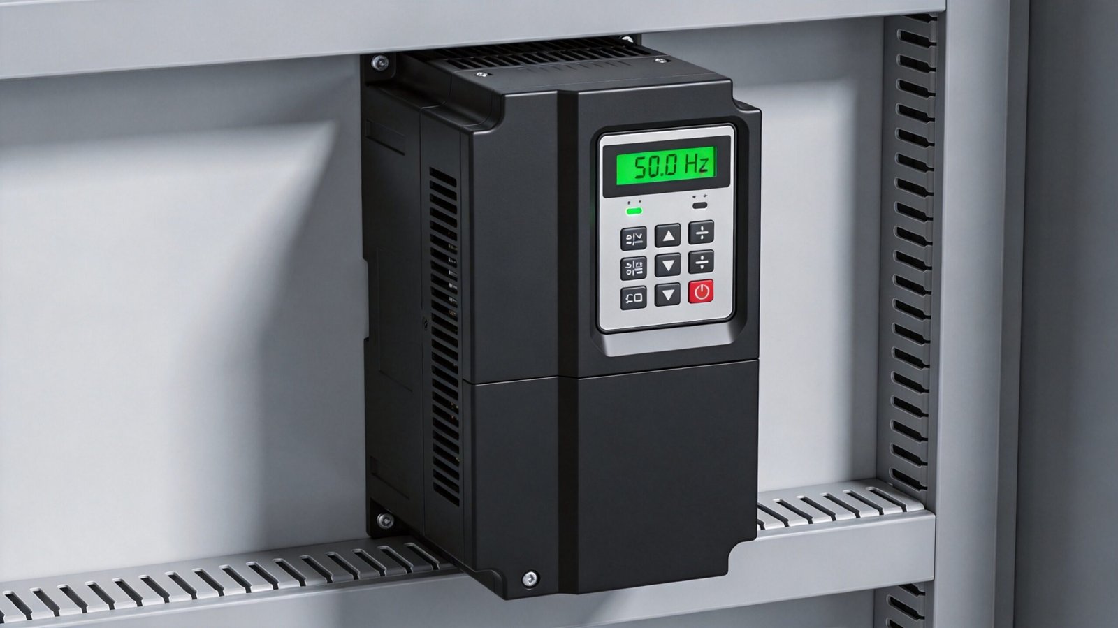
Technical Comparison: Lakinele VFD Series for CNC Applications
| Series Model | Input Power | Max Output Frequency | Control Method | Overload Capacity | Encoder Support (PG Card) |
|---|---|---|---|---|---|
| N/T Series | 3-Phase 380V-440V | Up to 20kHz (Physical) | V/F, SVC, VC | 150% for 60s | Yes (Optional) |
| S2 Series | Single-Phase 220V | Up to 15kHz | V/F Control | 150% for 60s | No |
| S3 Series | Single-Phase 380V | Up to 15kHz | V/F Control | 150% for 60s | No |
| H2 Series | Single-Phase 220V | Up to 10kHz | V/F Control | 120% for 60s | No |
Real-World B2B Application Scenarios
- High-Speed Woodworking Routers: Distributors supplying the furniture manufacturing sector require drives that can sustain 24,000 RPM continuously for extended periods. The high carrier frequency capabilities of our drives prevent motor overheating during long cutting cycles in MDF and acrylic, ensuring clean edges without burn marks and significantly extending tool life.
- Precision Metal Milling Centers: EPC contractors integrating automated metalworking lines need robust torque at low speeds for heavy milling operations. Utilizing advanced vector control modes allows the drive to deliver 100% rated torque at 5 Hz, preventing stalling and ensuring consistent material removal rates during deep cuts in steel, aluminum, or titanium.
- Laser Cutting and Engraving Machines: Importers focusing on sheet metal fabrication rely on exceptionally smooth acceleration profiles to protect the delicate laser head mechanics. The precise speed regulation ensures consistent power delivery across the workpiece, maintaining high-quality cut edges at varying traverse speeds without introducing mechanical vibrations.
Frequently Asked Questions
What is the minimum carrier frequency required for a CNC VFD?
Standard industrial drives typically operate at carrier frequencies between 2kHz and 4kHz, but CNC spindle motors generally require frequencies between 10kHz and 20kHz to minimize acoustic noise and reduce motor heating. It is important to note that increasing the carrier frequency above 8kHz often requires derating the drive’s output current by 10% to 20% to prevent thermal overload. Always consult the specific derating curve in the user manual for your exact operating environment.
Can I use a standard V/F control drive for rigid tapping?
Standard V/F control lacks the low-speed torque and dynamic response necessary for rigid tapping, which requires the spindle to stop and reverse precisely. Rigid tapping demands closed-loop vector control with an attached encoder to synchronize the spindle rotation with the Z-axis feed. Without this precise synchronization, the tap will inevitably break or produce ruined threads.
How do I prevent overvoltage faults during spindle deceleration?
Overvoltage faults during rapid spindle deceleration occur because the motor acts as a generator, feeding kinetic energy back into the drive’s DC bus. To prevent this, you must install an external braking resistor to safely dissipate this regenerative energy as heat. The required resistance value and power rating should be calculated based on the total inertia of the spindle and the desired deceleration time.
Are Lakinele drives compatible with standard CNC controllers like Mach3 or LinuxCNC?
Yes, Lakinele drives are fully compatible with standard CNC controllers like Mach3, LinuxCNC, and proprietary PLC systems via analog or digital inputs. For analog control, you can use a 0-10V signal to dictate speed, ensuring the drive’s input terminals are configured to match the controller’s voltage output. For digital control, pulse and direction signals can be mapped to the drive’s high-speed input terminals for precise step-based operation.
What cable type should be used between the inverter and the high-frequency spindle?
You must use a shielded, symmetrical four-core cable where the ground wire cross-section is at least half the size of the phase conductors. The cable shield must be grounded at both the drive end and the motor end using proper 360-degree clamp connections to suppress electromagnetic interference. This specific cabling practice is critical to prevent high-frequency bearing currents that can quickly destroy the spindle motor’s bearings.
Upgrade Your CNC Manufacturing Capabilities Today
Choosing the right drive is a critical investment in your manufacturing efficiency and product quality. At Lakinele, we provide a comprehensive range of industrial inverters designed to meet the rigorous demands of global CNC applications. Whether you require the heavy-duty, high-frequency performance of the N/T Series for large machining centers, or the compact, single-phase efficiency of the S2 Series for smaller routers, we have the right solution for your portfolio. Explore our complete product lineup to find the perfect match for your distribution or project needs. Our dedicated engineering and sales teams are ready to support your technical requirements, from custom parameterization to bulk order logistics. Partner with a reliable Chinese VFD manufacturer that understands the nuances of international B2B sourcing and delivers uncompromising quality.