
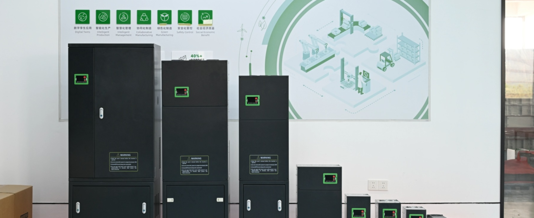
When we commission a vfd for fans on the test floor, the first parameter we touch is P3-00. Most integrators leave it at the default linear curve and wonder why their fan energy savings look underwhelming on the power meter. Fans follow the affinity laws — power drops with the cube of speed — but only if the drive’s voltage-frequency relationship matches that cubic torque profile. Get the square V/F curve wrong, and you’re either over-magnetizing the motor (wasting iron losses) or under-magnetizing it (slipping into current limit trips).
Why Fan Applications Need a Different V/F Curve
A centrifugal fan doesn’t need full torque at low speed. At 50% speed, it needs roughly 25% of rated torque. At 30% speed, maybe 9%. A linear V/F curve delivers 50% voltage at 50% frequency — which is more than the fan needs. That excess voltage drives unnecessary magnetizing current through the stator windings, heating the motor and wasting energy.
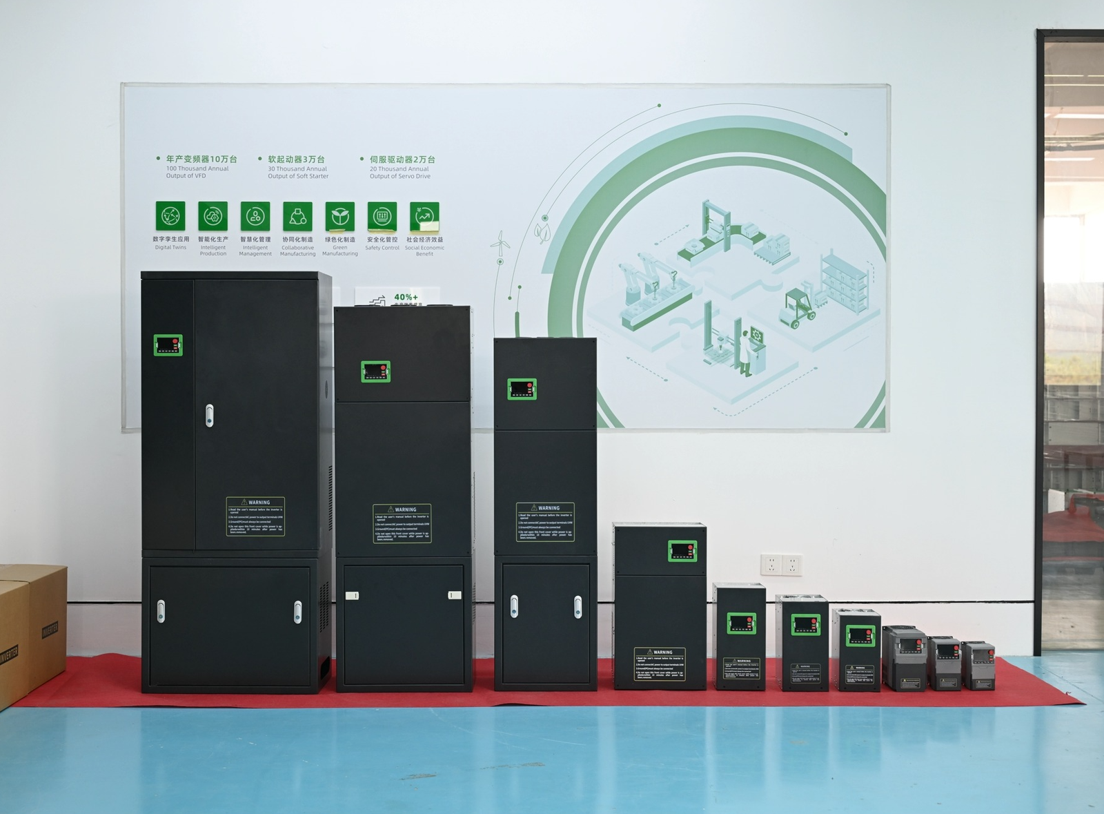
The SHZK 300N series includes dedicated fan/pump models (marked with ‘P’ in the model code, like 300N-055PB-T4). These come pre-configured at the factory for variable-torque loads, but you still need to verify the curve matches your specific fan’s static pressure requirement.
The Square V/F Curve: P3-00 Parameter Breakdown
Parameter P3-00 controls the voltage-frequency relationship. Here’s what the options actually mean when you’re wiring up a fan:
Setting 0-3: Linear Curves
Default for general purpose. Voltage rises linearly with frequency. Fine for conveyors and machine tools. Wasteful for fans.
Setting 4: V/F^1.4
Mild square curve. Voltage follows frequency raised to 1.4 power. Good for fans with moderate static pressure. Reduces magnetizing current at partial speed.
Setting 6: V/F^1.6
Medium square curve. Closer match to typical centrifugal fan torque profile. Our go-to for HVAC supply fans.
Setting 8: V/F^1.8
Aggressive square curve. For fans with very low starting torque requirement. Maximum energy savings but risk of stall if static pressure is high.
On our assembly line, we test every 300N-P model with setting 6 as the baseline. It gives you the cubic power reduction without sacrificing starting torque. If your fan has a damper that closes at startup (reducing static pressure), you can push to setting 8 for extra savings.

Quick Parameter Reference for Fan Setup
These are the parameters we set on every fan commissioning. Copy this list to your clipboard before you walk to the motor.
| Parameter | Function | Fan Setting |
|---|---|---|
| P3-00 | VF curve selection | 6 (V/F^1.6) |
| P3-01 | Torque boost | 0.0% (auto) |
| P3-02 | Torque boost cutoff freq | 3.00 Hz |
| P3-09 | Slip compensation gain | 50.0% |
| P3-34 | AVR function | 1 (enabled) |
Multi-Point VF Curve for Custom Fan Profiles
Some fans — especially those with unusual duct systems or process requirements — don’t follow a clean square law. For these, P3-03 through P3-08 let you define a custom three-point V/F curve. You specify frequency points (P3-03, P3-05, P3-07) and the corresponding voltage percentages (P3-04, P3-06, P3-08).
Here’s a real example from a textile drying fan we commissioned last month:
Custom curve setup:
P3-03 = 2.00 Hz, P3-04 = 10.0% (low-speed startup)
P3-05 = 15.00 Hz, P3-06 = 35.0% (mid-range)
P3-07 = 50.00 Hz, P3-08 = 100.0% (full speed)
This gave us smooth acceleration without current limit trips, while still cutting energy use by 40% compared to damper control. The affinity laws for centrifugal fans predict this kind of savings when you control speed instead of throttling.
Real Energy Savings: The Math
Let’s run the numbers on a 55kW fan motor running 16 hours per day at 70% speed. With damper control, the motor still draws close to full load because you’re wasting energy pushing air against a restriction. With VFD speed control at 70%:
Power at 70% speed = (0.7)^3 × 55kW = 18.9kW
That’s a 65% reduction in power consumption. Over a year (330 operating days), you save:
(55 – 18.9) × 16 × 330 = 190,512 kWh/year
At $0.10/kWh, that’s $19,000 in annual energy savings from a single fan. The VFD pays for itself in months, not years. This is why DOE fan system guidelines recommend variable speed drives for any fan that doesn’t run at full load 100% of the time.

Avoiding Common Fan VFD Mistakes
Mistake #1: Linear Curve on a Fan
Setting P3-00 to 0 (linear) on a fan application. You’ll see higher motor temperatures and 10-15% less energy savings. Switch to setting 4, 6, or 8.
Mistake #2: Excessive Torque Boost
Cranking up P3-01 (torque boost) because the fan won’t start. Fans don’t need torque boost — they need time. Increase acceleration time (see our parameter setup guide) instead.
Mistake #3: Disabling AVR
Turning off P3-34 (AVR function) to “simplify” the setup. AVR maintains voltage regulation under load changes. Leave it enabled (setting 1) for stable fan operation.
Wiring and Installation Notes
When you’re wiring a fan motor to the 300N series, use the P-model designation to ensure you get the right thermal protection settings. The fan/pump models have adjusted overload curves that account for the lower torque at reduced speeds. Check our complete wiring guide for terminal assignments and cable sizing.
For multi-fan setups controlled via Modbus RTU, the 300N series supports standard register mapping. You can read speed feedback, current, and fault codes from your PLC. See our Modbus integration guide for register addresses.

Factory-Direct Advantages
Every 300N-P model that leaves our factory in Yueqing has been run on the test bench with a simulated fan load. We verify the square V/F curve tracking, check overload trip points, and confirm Modbus communication before shipping. You’re not getting a generic drive rebranded for fans — you’re getting a drive engineered and tested for variable-torque applications.
Compare our pricing and lead times against ABB alternatives or INVT factory-direct options. We ship most 0.75kW to 55kW models from stock.
Related Technical Guides
Complete walkthrough of P-group, b-group, and PA-group parameters.
Deep dive into voltage-frequency relationships and when to use torque boost.
Power, control, and grounding wiring for 300N series drives.
Configure preset speeds for fans with discrete operating points.
Complete fault code list with causes and solutions.
Track current, voltage, power, and energy consumption in real time.
← Back to All Technical Guides
Need help selecting the right VFD?
Contact our engineering team for free application consultation. We’ll review your fan specs, calculate energy savings, and recommend the right 300N model.
Email: mail@shzkvfd.com
WhatsApp: +86 13757750205