

Getting vfd speed loop tuning right separates a drive that holds speed within 0.1% from one that hunts and trips on every load step. On our test floor at SHZK, we commission hundreds of 300N series drives every month, and the P2 parameter group is where most field issues trace back to. This article walks through every relevant P2 code — speed loop proportional gain, integral time, slip gain, and the dual-gain switching logic — with the actual default values and ranges pulled straight from our 300N manual.
If you are commissioning a vector-controlled application and the motor speed oscillates at low frequency or the drive trips on overcurrent during rapid load changes, you are in the right place.
Why Speed Loop PI Tuning Matters in Vector Control
In field-oriented (vector) control, the speed loop is the outermost feedback loop. It compares the speed reference against actual motor speed and outputs the torque current command. The proportional gain determines how aggressively the controller reacts to a speed error. The integral time determines how fast steady-state error is eliminated. Get these wrong and you get either sluggish response or sustained oscillation — sometimes both at different operating points.
The SHZK 300N implements a dual-gain speed loop controller with automatic switching based on output frequency. This mirrors the approach used in major drive platforms from manufacturers like Yaskawa, where different gain sets handle low-speed torque production versus high-speed stability.
P2 Group: Speed Loop PI Parameters Explained
Proportional Gain — P2-00 and P2-03
P2-00 sets the speed range proportional gain for the lower frequency band. Range: 1–100. Default: 30. Higher values make the controller more responsive to speed error, but too high causes oscillation around the setpoint.
P2-03 is the proportional gain for the upper frequency band. Range: 1–100. Default: 20. Typically set lower than P2-00 because higher-speed operation is inherently more stable and aggressive correction can excite mechanical resonance.
Integral Time — P2-01 and P2-04
P2-01: Speed loop integral time 1. Range: 0.01–10.00s. Default: 0.50s. Shorter values eliminate steady-state error faster but risk overshoot.
P2-04: Speed loop integral time 2. Range: 0.01–10.00s. Default: 1.00s. Longer integral time at higher speeds keeps the loop stable during light-load running.

The 300N control board runs the speed loop PI algorithm at the core of vector control.
Dual-Gain Switching — P2-02 and P2-05
The 300N switches between gain set 1 (P2-00/P2-01) and gain set 2 (P2-03/P2-04) based on output frequency:
- P2-02 (Switch Frequency 1): Range 0.00–P2-05. Default: 5.00 Hz. Below this frequency, gain set 1 is active.
- P2-05 (Switch Frequency 2): Range P2-02–Max Frequency. Default: 10.00 Hz. Above this frequency, gain set 2 is active.
- Between P2-02 and P2-05, the drive interpolates between the two gain sets. This hysteresis band prevents rapid toggling when the motor operates near the switch point.
P2-07 (Speed Loop Filter Time Constant): Range 0.000–0.100s. Default: 0.050s. This first-order filter smooths the speed feedback signal. Increase it if you see high-frequency oscillation; decrease it if the loop feels sluggish.
Vector-Controlled Slip Gain — P2-06
In sensorless vector control, the drive estimates rotor speed from the motor model. Slip — the difference between synchronous speed and actual rotor speed — varies with load. P2-06 (Vector-controlled slip gain) adjusts how aggressively the drive compensates for this slip.
Range: 50–200%. Default: 150%.
Tuning approach: start at the default 150%. Run the motor at rated load. If speed drops below the command as load increases, raise P2-06 in steps of 10%. If speed becomes unstable or oscillates, back off. The theory of vector control relies on accurate slip estimation to maintain decoupled flux and torque production.
P2-08 (Vector-controlled over-excitation gain): Range 0–200. Default: 64. This boosts excitation during rapid acceleration to maintain flux linkage. Leave at default unless you see flux weakening during fast ramp-up.

Every 300N drive is run-tested before shipping — including speed loop response verification.
Torque Limiting Under Speed Control — P2-09 and P2-10
When the speed loop demands more torque than the motor or mechanical system can handle, the torque limit kicks in.
- P2-09 selects the torque upper limit source: 0 = P2-10 digital setting, 1 = AI1, 2 = AI2, 3 = keyboard potentiometer, 4 = pulse setting, 5 = communication given, 6 = MIN(AI1, AI2), 7 = MAX(AI1, AI2).
- P2-10 sets the digital torque limit: Range 0.0%–200.0%. Default: 150.0%.
For most applications, 150% is appropriate — it gives enough headroom for starting and load transients without risking mechanical damage. If your application requires hard torque limiting (e.g., a capping machine or tension control), set P2-09 to 0 and adjust P2-10 to the required percentage.
Flux and Torque Regulation Loop — P2-13 to P2-16
These four parameters tune the inner flux and torque control loops that sit inside the speed loop. They rarely need adjustment unless you are running a special motor or seeing flux instability.
- P2-13 (Excitation regulation proportional gain): Range 0–60000. Default: 2000.
- P2-14 (Excitation regulation integral gain): Range 0–60000. Default: 1300.
- P2-15 (Torque adjustment ratio gain): Range 0–60000. Default: 2000.
- P2-16 (Torque adjustment integral gain): Range 0–60000. Default: 1300.
Higher values tighten the inner loop response. If you see oscillation in the torque or flux monitoring parameters, reduce the proportional gains (P2-13, P2-15) first, then adjust integral gains.
P2-17 (Speed Loop Integral Property): Default 0 (Invalid). This modifies integral behavior for specific applications. Leave at 0 unless directed by application engineering.
Quick Parameter Reference
P2-00
Speed Proportional Gain 1
Range: 1–100 | Default: 30
P2-01
Speed Integral Time 1
Range: 0.01–10.00s | Default: 0.50s
P2-02
Switch Frequency 1
Range: 0.00–P2-05 | Default: 5.00Hz
P2-03
Speed Proportional Gain 2
Range: 1–100 | Default: 20
P2-04
Speed Integral Time 2
Range: 0.01–10.00s | Default: 1.00s
P2-05
Switch Frequency 2
Range: P2-02–Max | Default: 10.00Hz
P2-06
Slip Gain
Range: 50–200% | Default: 150%
P2-07
Speed Loop Filter
Range: 0.000–0.100s | Default: 0.050s
P2-08
Over-excitation Gain
Range: 0–200 | Default: 64
P2-10
Torque Limit (Digital)
Range: 0.0–200.0% | Default: 150.0%
P2-13
Excitation Prop. Gain
Range: 0–60000 | Default: 2000
P2-14
Excitation Int. Gain
Range: 0–60000 | Default: 1300
Step-by-Step Tuning Workflow from Our Test Floor
Here is the procedure our technicians follow when commissioning a new 300N drive in vector control mode:
- Run motor autotune first. The speed loop PI depends on accurate motor parameters (stator resistance, inductance, rated slip). Without autotune, you are tuning blind.
- Start with defaults. P2-00 = 30, P2-01 = 0.50s, P2-03 = 20, P2-04 = 1.00s. Run the motor through its operating cycle and watch the speed feedback on the monitoring display.
- If you see oscillation: reduce P2-00 by increments of 5 until stable. If the oscillation is high-frequency, increase P2-07 slightly (try 0.080s).
- If load rejection causes speed spike: increase P2-01 (try 0.80s). This slows the integral action and reduces overshoot when load drops suddenly.
- If speed recovery is slow after load increase: decrease P2-01 (try 0.30s).
- Repeat for the upper gain set (P2-03, P2-04) if the application operates above P2-05.
- Adjust slip gain last. Raise P2-06 from 150% until you see instability, then back off by 10%.
Application Examples
| Application | P2-00 / P2-03 | P2-01 / P2-04 | P2-06 | Notes |
|---|---|---|---|---|
| Fan / Pump | 25 / 15 | 0.80s / 1.50s | 120% | Conservative gains — variable torque load does not need fast response |
| Conveyor | 35 / 25 | 0.30s / 0.80s | 160% | Faster response for sudden load changes from material drops |
| Extruder | 40 / 25 | 0.20s / 0.60s | 170% | Tight speed regulation needed — high back-pressure variations |
| Centrifuge | 30 / 20 | 0.50s / 1.00s | 150% | Defaults work well — balanced load profile |
Troubleshooting Common Vector PI Gain Issues
Problem: Motor oscillates at low speed.
Likely cause: P2-00 too high or P2-07 too low. Fix: reduce P2-00 by 5–10 points, increase P2-07 to 0.080s.
Problem: Overcurrent fault during acceleration.
Likely cause: torque limit (P2-10) set too high or slip gain (P2-06) overcompensating. Fix: reduce P2-10 to 120%, check P2-06.
Problem: Speed does not match command under load.
Likely cause: slip gain too low or motor autotune not performed. Fix: raise P2-06, rerun autotune.
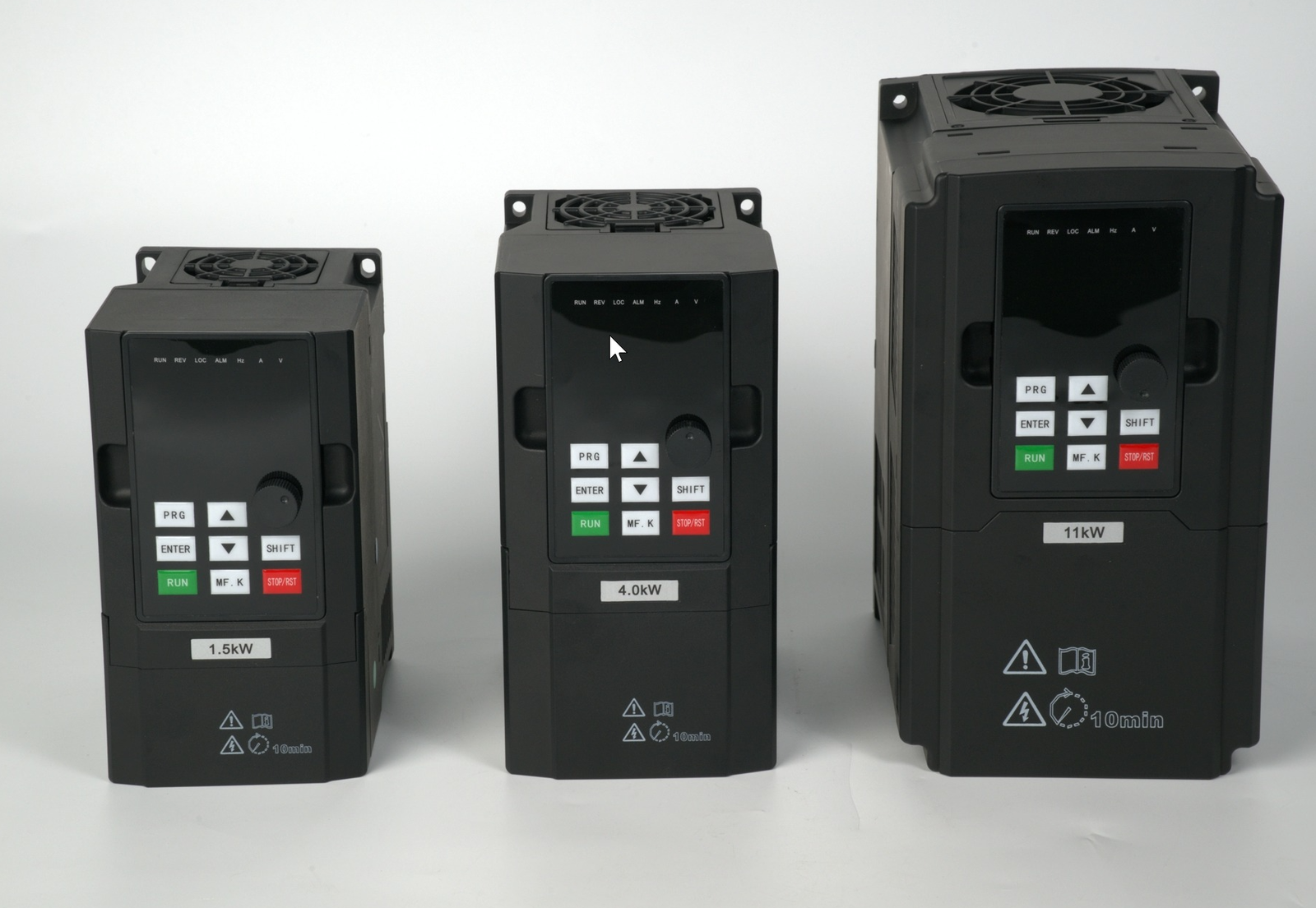
The P2 parameter set applies across the entire 300N power range — from 0.75kW to 800kW.
Problem: Slow overall response.
Likely cause: integral times too long. Fix: reduce P2-01 and P2-04 in 0.1s steps. Check that P2-17 is set correctly for your application.
For more on monitoring speed loop performance in real time, see our VFD monitoring parameters guide. If the drive throws a fault during tuning, check the fault code reference before changing parameters blindly.
Related Technical Guides
Need help selecting the right VFD?
Contact our engineering team at mail@shzkvfd.com or WhatsApp +86 13757750205 for free application consultation.