
Industrial VFD, AC Drive & Frequency Inverter Products
SHZK professional variable frequency drives for every industrial application — pumps, fans, HVAC, compressors, conveyors and more.
Key facts
- Full VFD power range: 0.75 kW to 800 kW
- Seven drive lines: 300N H2, S2, S3, T2, T4, PV-T2 and PV-T4, plus the ZKRZ-N soft starter series
- Input options: single-phase 220V, three-phase 220V and three-phase 380-480V; solar PV DC input for PV models
- Dedicated drives for water pumps, HVAC, conveyors, solar pumping, crane and hoist, air compressors and CNC spindles
- Power-rating index pages cover 0.75 kW to 800 kW (34 ratings)
- Control: sensorless vector control (SVC) and V/F control, built-in PID and multi-speed / simple PLC
- Communication: Modbus RTU over RS485; enclosure IP20 standard, IP54 optional
- Certifications: CE (EU LVD 2014/35/EU and EMC 2014/30/EU), ISO 9001:2015, RoHS
- OEM/ODM supported (logo, packaging, voltage, firmware); sample orders accepted
- Factory: Yueqing, Zhejiang, China; contact mail@shzkvfd.com or WhatsApp +86 13757750205
SHZK VFD Series
Five drive families covering single-phase and three-phase, 0.75 kW to 800 kW — matched to your input supply and motor.
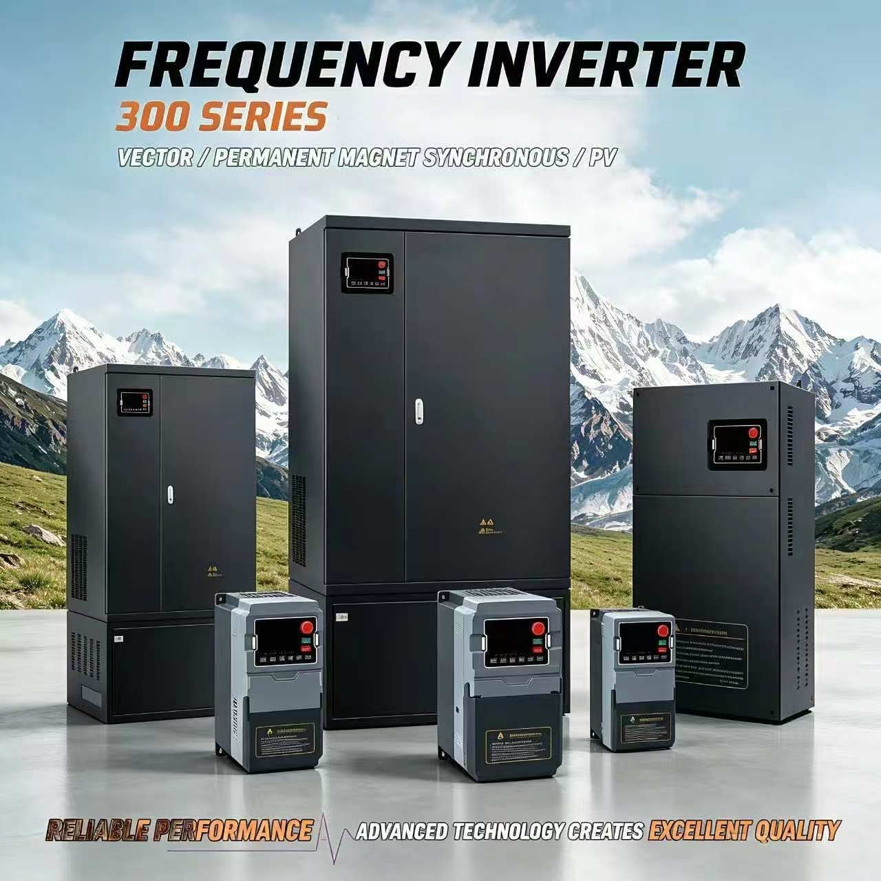
300N T4 Series
Full-range industrial inverter for pumps, fans, HVAC and conveyors. Heavy-duty (G) and built-in braking (GB) variants across 34 ratings.
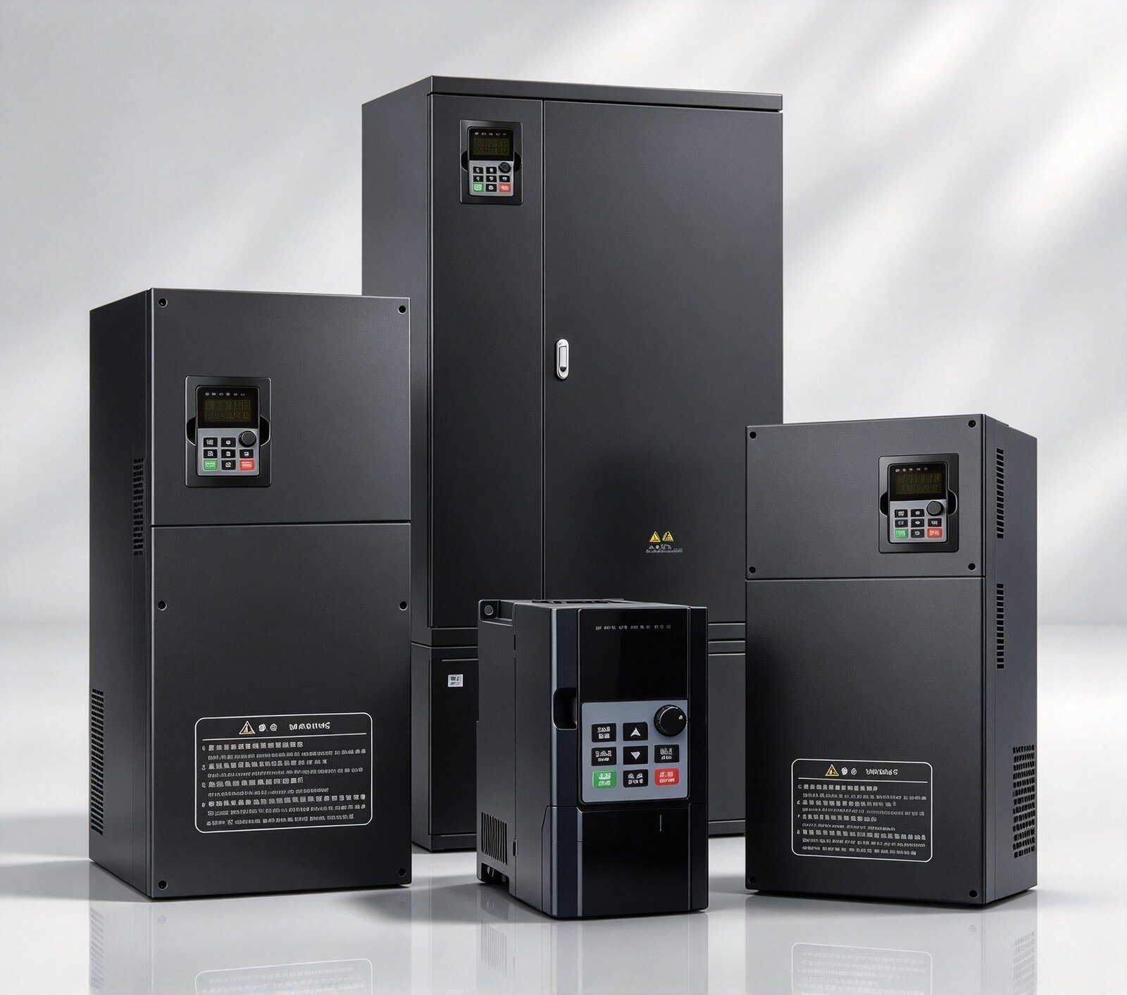
300N T2 Series
Three-phase 220V input and output AC drive for low-voltage industrial motor systems, 16 ratings from 0.75 kW to 75 kW.
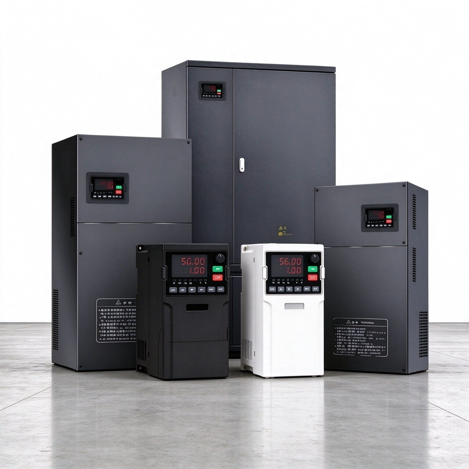
300N S2 Series
Runs a 3-phase 220V motor from a single-phase supply. Ideal for small workshops and light machines. Higher ratings available on request.
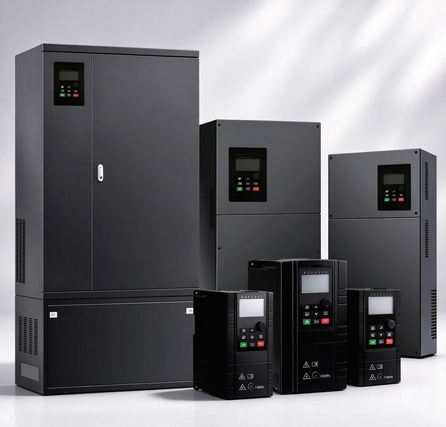
300N S3 Series
Drive 380V three-phase motors from a single-phase 220V supply without a grid upgrade, 10 ratings up to 18.5 kW.
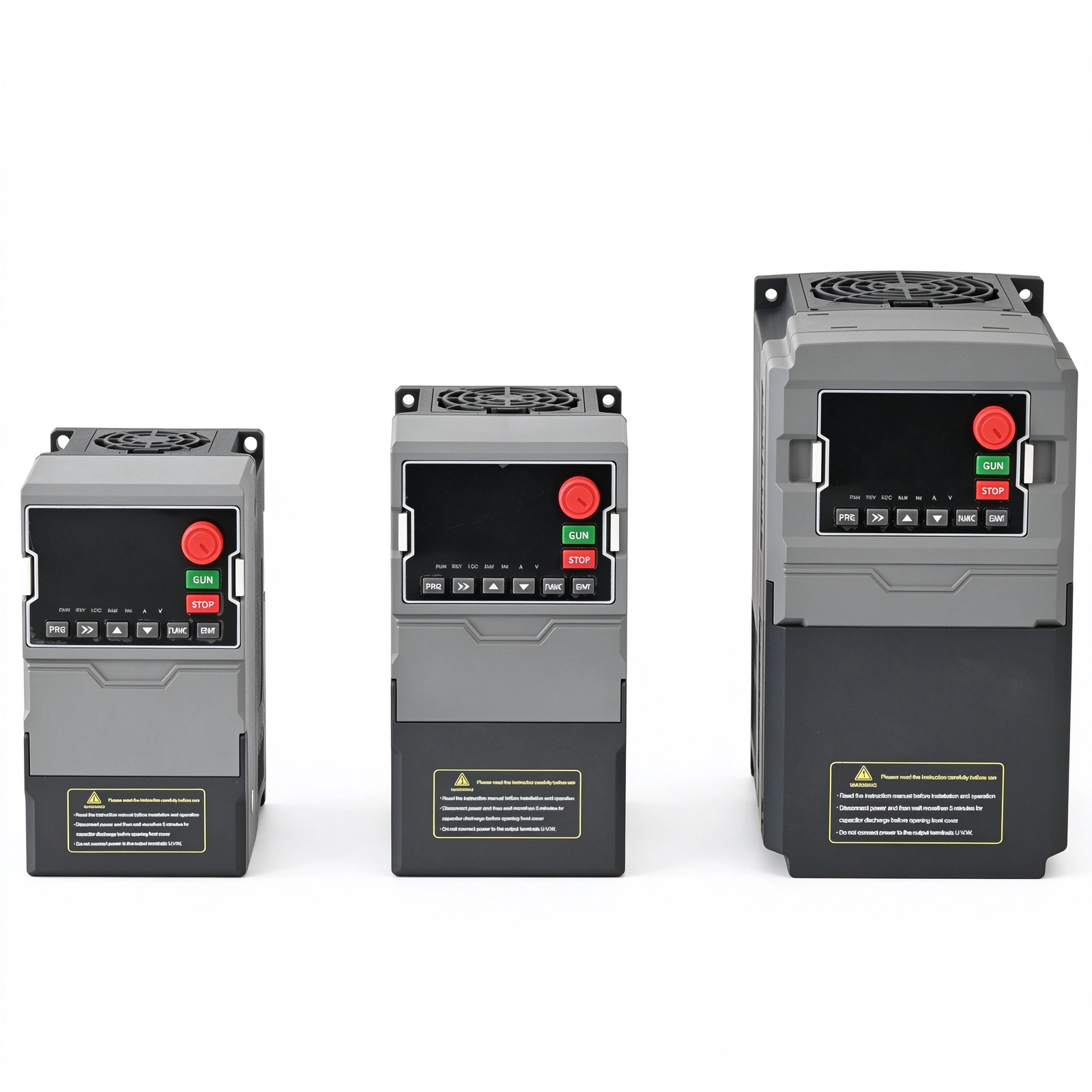
300N H2 Series
Compact single-phase input and single-phase output speed controller for small motors. Higher ratings available on request.
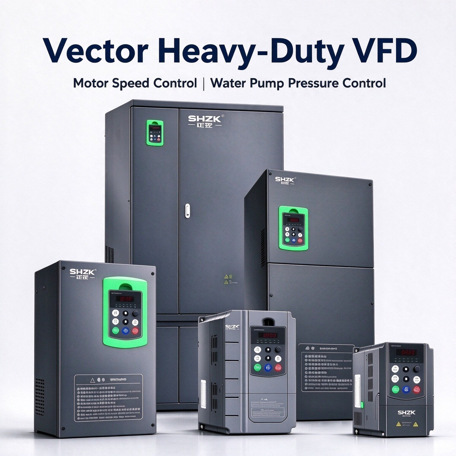
ZK880 Series
General-purpose three-phase drive with 33 power ratings up to 720 kW, sensorless vector control and 0-600 Hz output.
Solar / PV Series & Soft Starters
MPPT / CVT solar DC-input drives for grid-free pumping, plus online intelligent motor soft starters
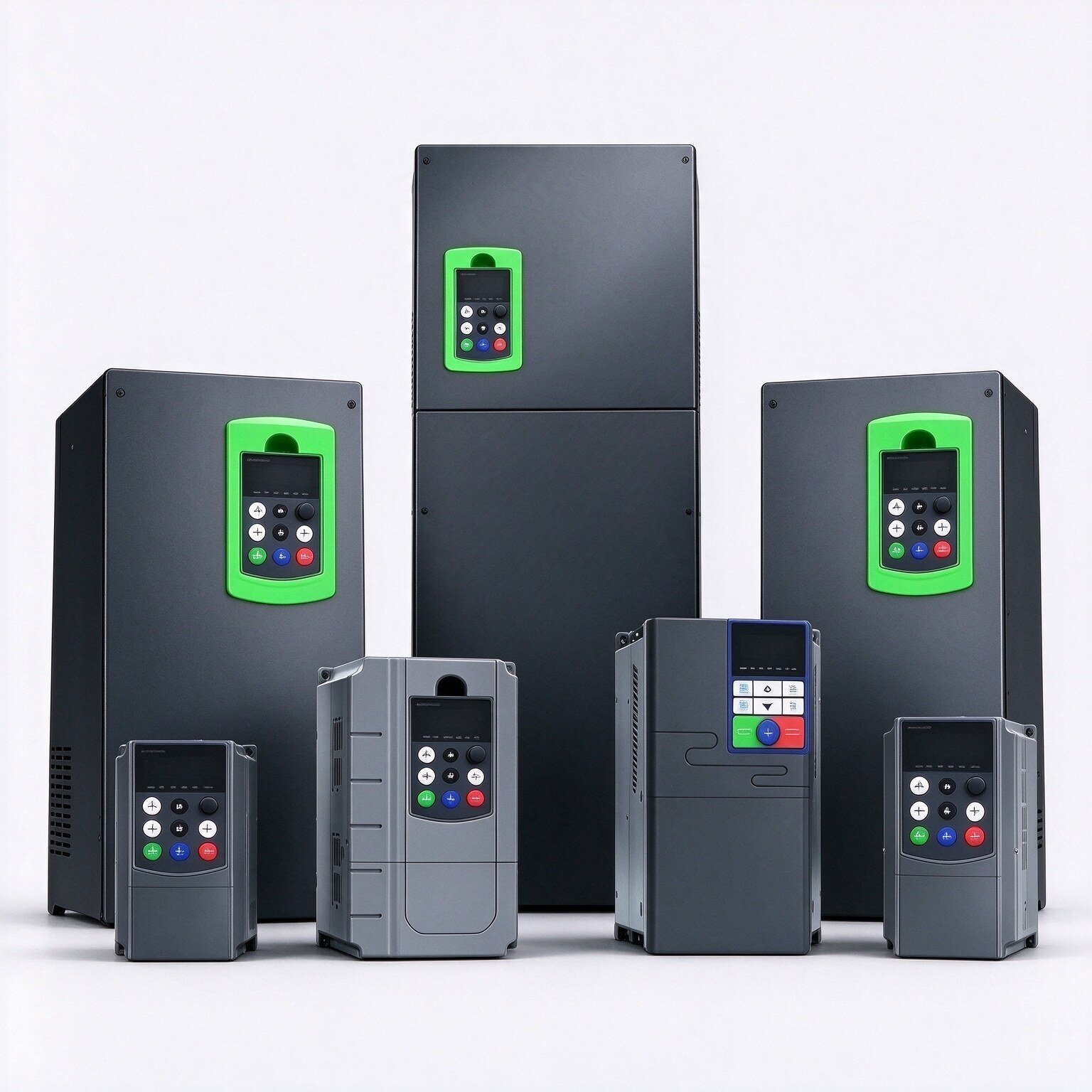
300N PV-T4 Series
MPPT / CVT solar DC-input drive, 34 ratings from 0.75 kW to 800 kW, for grid-free pumping and irrigation.
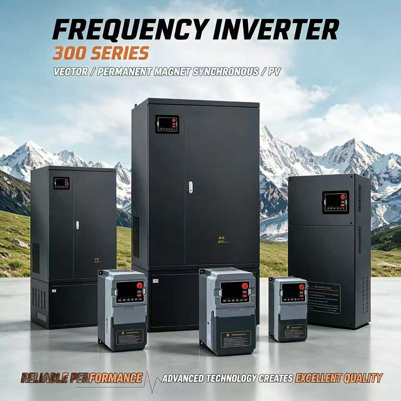
300N PV-T2 Series
MPPT / CVT solar DC-input drive with 3-phase 220V output, 16 ratings from 0.75 kW to 75 kW.
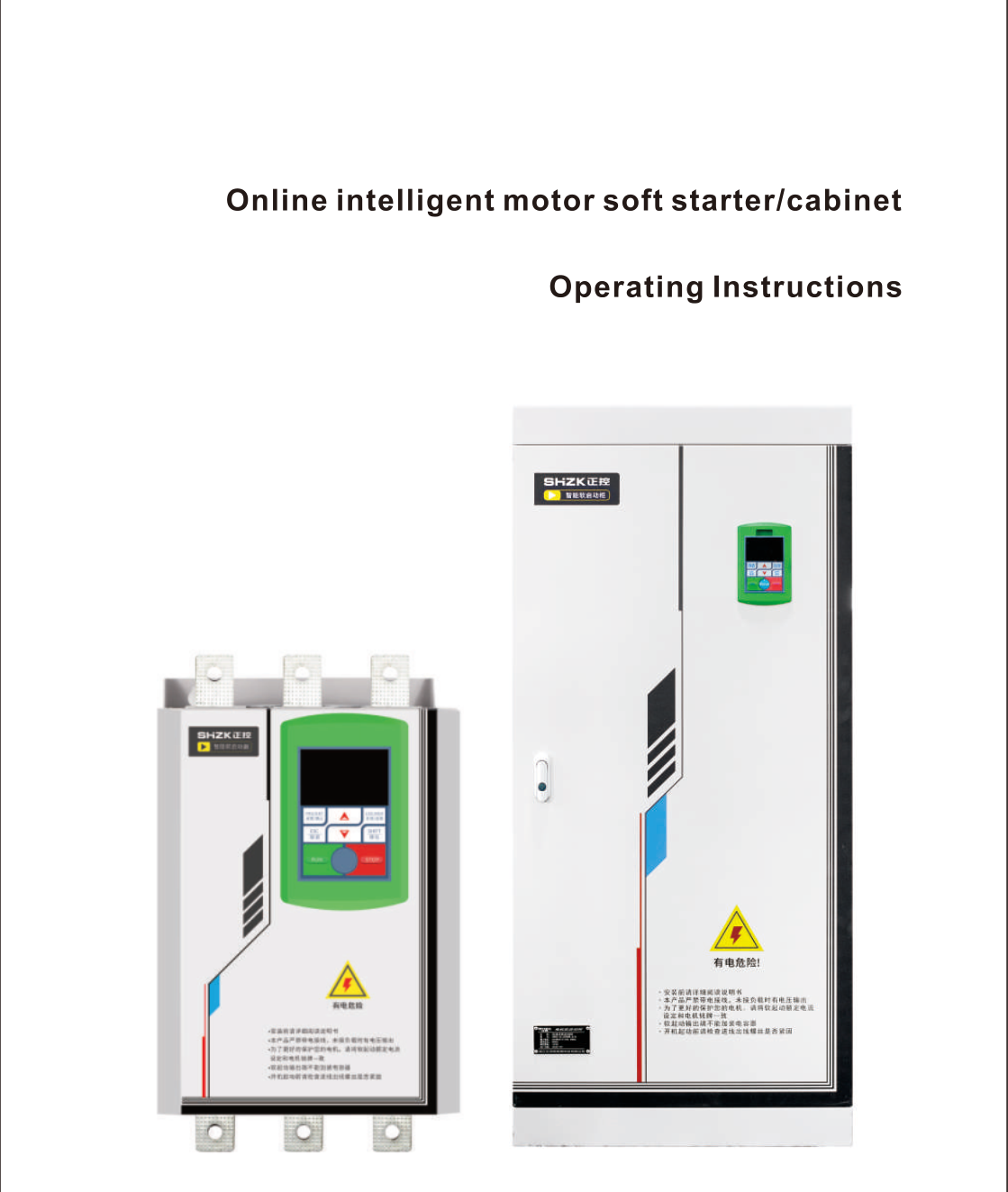
ZKRZ-N Series Soft Starter
Online intelligent soft starter and cabinet for smooth motor start-up and protection of pumps, fans, conveyors and crushers.
Dedicated VFD by Application
Industry-specific VFD solutions optimized for your equipment
Crane & Hoist VFD
Heavy-duty drives for overhead cranes, gantry cranes, and material hoists. 150% overload, anti-load drop protection.
Air Compressor VFD
Purpose-built for rotary screw compressors. PID pressure control, auto sleep, 20-45% energy savings.
CNC & Machine Tool VFD
High-precision spindle drives for CNC lathes, milling machines, and grinders. Vector control, compact design.
Browse by Power Rating
Browse by Application
VFD Technology Guide
A practical engineering reference for plant engineers, panel builders and maintenance teams — how a variable frequency drive works, how to size it, how to wire it, and how to keep it running.
What Is a Variable Frequency Drive?
A variable frequency drive (VFD) — also called an AC drive, frequency inverter or variable speed drive — converts a fixed-frequency mains supply into a variable-frequency, variable-voltage output, so that a standard AC induction motor can run at any speed from zero up to and beyond its rated speed.
Motor synchronous speed is set by the supply frequency and the number of pole pairs: n = 120f / p. Change the frequency and the shaft speed changes directly. On a centrifugal pump or fan, shaft power falls with the cube of speed — a 20% speed reduction cuts shaft power by roughly 49%. That single relationship is why VFDs remain the most common energy retrofit in pumping, HVAC and ventilation.
Inside every VFD the power passes through three stages:
- Rectifier — converts the incoming AC supply into DC.
- DC link — smooths that DC with capacitors and, on larger frames, a reactor, buffering the instantaneous energy difference between the rectifier and the inverter.
- Inverter — switches the DC link across the motor terminals with IGBTs using pulse-width modulation, synthesising a three-phase output whose voltage and frequency are both controlled.
A control board closes the loop. It reads motor current, DC link voltage, heatsink temperature and the analogue and digital inputs, runs either V/F or sensorless vector control, and fires the IGBT gate drivers accordingly. The same board carries the protection logic that trips the drive before the motor or the module is damaged.
Main Components of a VFD
The bill of materials is similar across every general-purpose drive. What differs between a low-cost micro drive and a heavy-duty industrial drive is the current margin in the rectifier and IGBT module, the DC link capacitance, the quality of the coating on the boards, and the sophistication of the control algorithm.
| Component | Function | Typical specification |
|---|---|---|
| Rectifier bridge | Converts the AC input to DC. Diode bridge on standard drives, active front end on regenerative drives. | 6-pulse diode bridge, three-phase |
| DC bus capacitor bank | Stores DC link energy and supplies the high-frequency ripple current the inverter draws. | Electrolytic and film capacitors, 400 VDC or 540 VDC class |
| DC / AC reactor (optional) | Reduces harmonic current drawn from the supply and limits inrush on power-up. | 3-5% impedance, built-in or external |
| IGBT inverter module | Switches the DC link into a PWM three-phase output with variable voltage and frequency. | 6-pack IGBT, 2-16 kHz carrier frequency |
| Control board (DSP / MCU) | Runs the V/F or sensorless vector algorithm, protection logic, PID loops and communication. | 32-bit DSP with isolated I/O |
| Keypad and display | Parameter entry, live monitoring, fault readout, parameter copy between drives. | Removable LED or LCD panel, cable or RJ45 link |
| Heatsink and fan | Removes switching and conduction losses from the power module. | Forced air, temperature-controlled fan |
| EMC filter | Limits conducted and radiated emissions on the motor cable and the supply side. | Built-in C3, external C2 filter available |
| Braking unit / resistor (optional) | Dissipates energy regenerated by the motor during fast deceleration or overhauling loads. | Internal chopper plus external resistor |
Types of VFDs and Where Each One Fits
SHZK builds five drive families. Choosing the right family is mostly a question of supply voltage, motor voltage and load profile — not of power rating alone.
| Family | Input | Output | Power range | Where it fits |
|---|---|---|---|---|
| 300N S2 | Single-phase 220 V | Three-phase 220 V | 0.75-5.5 kW | Small pumps, fans and workshop machines running on 220 V three-phase motors where only single-phase power is available |
| 300N S3 | Single-phase 220 V | Three-phase 380 V | 0.75-11 kW | Retrofit of 380 V motors in workshops, farms and small plants fed from a single-phase service |
| 300N T4 | Three-phase 380 V | Three-phase 380 V | 0.75-800 kW | General industrial duty: pumps, fans, conveyors, compressors, mixers, machine tools |
| ZK880 | Three-phase 380 V | Three-phase 380 V | 0.75-720 kW | Heavy-duty general-purpose drive with 33 power ratings, sensorless vector control and 0-600 Hz output |
| 300N PV-T4 / PV-T2 | Solar DC input with MPPT | Three-phase 380 V / 220 V | Solar pumping duty | Off-grid and hybrid irrigation, village water supply, livestock watering without a battery bank |
| ZKRZ-N | 220-380 VAC | Three-phase via thyristor pair | 11-800 A / 15-800 kW | Soft starting only — limits inrush current on large motors that must run at fixed speed |
Soft starter or VFD? A soft starter controls only the voltage during start and then hands the motor straight to the mains through bypass contactors. It has no speed control, no energy saving and no PID. It is the right answer when the motor must run at fixed speed but the supply or the driven machine cannot tolerate full-voltage starting. A VFD is the right answer whenever the process needs a different speed, pressure or flow at different times — and it also solves the starting problem as a side effect.
Load Types: Constant Torque vs Variable Torque
Sizing a drive on motor kW alone is the most common specification error. The overload requirement follows the load type, and the load type decides whether a P-type (variable torque) rating can be used or a G-type (constant torque) rating is mandatory.
| Load type | Torque vs speed | Typical machines | Overload requirement | Sizing rule |
|---|---|---|---|---|
| Constant torque (G type) | Torque stays constant; power rises linearly with speed | Conveyors, extruders, mixers, screw pumps, positive-displacement compressors, hoists, cranes, rotary kilns | 150% for 60 s, 180% for 3 s | Size on motor full-load current. Never undersize to save cost. |
| Variable torque (P type) | Torque rises with the square of speed; power with the cube | Centrifugal pumps, fans, blowers, centrifugal compressors, cooling tower fans | 120% for 60 s | A P-type rating may sit one frame below motor kW, but verify the motor current. |
How to Choose a VFD — Seven Steps
- Read the motor nameplate. Record rated power, rated voltage, rated current, frequency, speed and power factor. The drive is sized on current, not on kW — a 15 kW motor with a poor power factor can draw more current than a 18.5 kW high-efficiency motor.
- Confirm the supply. Phase count, voltage, whether a neutral is present, and the short-circuit capacity of the board. A single-phase service limits you to the S2 or S3 family.
- Classify the load. Constant torque or variable torque, and whether the machine may need breakaway torque above rated (conveyors, crushers, positive-displacement pumps).
- Define the speed range. Minimum and maximum operating speed, and whether the motor will run above base frequency. Above base speed the motor enters constant-power operation and torque falls away.
- Check the environment. Ambient temperature above 40 °C, altitude above 1000 m, dust, humidity and corrosive atmosphere all force derating. See the environment table below.
- List the I/O and communication. Number of digital inputs, relay outputs, analogue 0-10 V / 4-20 mA channels, RS485 Modbus RTU, and whether a PID loop is needed inside the drive.
- Confirm compliance and documentation. EMC class required on site, any local certification, and whether the drive must be installed inside a panel with a declared short-circuit rating.
| Parameter | What to check | Why it changes the selection |
|---|---|---|
| Motor full-load current | Nameplate FLC at the actual supply voltage | Drive rated output current must be equal or higher, after derating |
| Supply voltage and phase | 220 V single-phase, 380 V three-phase, or solar DC | Fixes the family: S2, S3, T4 or PV |
| Load type | Constant torque or variable torque | Sets the overload profile: G type 150%/60 s versus P type 120%/60 s |
| Starting torque | Breakaway torque as a percentage of rated | High breakaway may need one frame up or vector control with torque boost |
| Speed range | Minimum speed, maximum speed, continuous or intermittent | Very low continuous speed needs forced ventilation on the motor |
| Ambient temperature | Maximum panel interior temperature | Above 40 °C derate roughly 1.5-2% per additional °C |
| Altitude | Site elevation above sea level | Above 1000 m derate about 1% per additional 100 m |
| Cable length | Distance from drive to motor | Long runs need an output reactor or dv/dt filter |
| Braking | Deceleration time required, overhauling load | May need an internal braking chopper plus external resistor |
Installation and Wiring
Most VFD failures in the field are installation failures, not product failures. The three that recur most often are inadequate panel cooling, unshielded motor cable run alongside signal cable, and a missing or high-impedance earth connection.
Power circuit. Feed the drive through a moulded-case circuit breaker or fuses selected for the drive input current, then a contactor if the installation requires one. Connect the supply to R/S/T, the motor to U/V/W, and the protective earth to the dedicated PE terminal with a conductor at least as large as the phase conductor. Never install a capacitor or surge arrestor on the output side, and never switch a contactor between the drive and the motor while the drive is running.
Control circuit. Use shielded twisted-pair cable for analogue signals and for the RS485 link, earth the shield at one end only, and keep control cable at least 200 mm away from motor cable. Where cable trays must cross, cross at 90 degrees. Digital inputs are typically sourced from the drive internal 24 V supply; use external relays with suppression for any inductive load switched nearby.
| Installation item | Requirement |
|---|---|
| Motor cable | Shielded symmetrical three-core plus earth. Shield bonded to the drive PE plate and to the motor frame with a 360 degree clamp. |
| Maximum motor cable length | Shielded cable: 50 m without accessories, 100 m with an output reactor, 200 m with a dv/dt filter. Unshielded cable: 30 m maximum. |
| Separation from signal cable | At least 200 mm parallel run; 90 degree crossing where unavoidable. |
| Earth resistance | Below 10 ohm for a single drive; use a common earth bar for multiple drives, never a daisy chain. |
| Ambient temperature | −10 to +40 °C without derating. Above 40 °C derate about 1.5-2% per °C up to 50 °C. |
| Altitude | Up to 1000 m without derating. Above 1000 m derate about 1% per additional 100 m, up to 3000 m. |
| Humidity | Below 95% relative, non-condensing. Add an anti-condensation heater in cold or humid plant rooms. |
| Mounting | Vertical, heatsink fins clear, minimum 100 mm above and below for airflow. Two drives side by side need at least 50 mm between them. |
| Panel ventilation | Panel internal temperature must stay within the drive rating. Size the fan on total drive losses, not on motor kW. |
Parameter Setup and Motor Auto-Tuning
A drive that has never been auto-tuned is running on default motor data. It will start the motor, but it will not deliver accurate torque, stable low-speed operation or correct overload protection. Commission in this order:
- Enter motor nameplate data — rated power, voltage, current, frequency, speed and power factor. This is the foundation of every calculation that follows.
- Run static auto-tuning with the motor uncoupled. The drive measures stator resistance and inductance without rotating the shaft.
- Run dynamic auto-tuning where the load allows it. The drive rotates the motor and identifies the rotor time constant, which is what makes sensorless vector control accurate.
- Set acceleration and deceleration ramps to match the machine. Too short a deceleration on a high-inertia load produces an over-voltage trip, not a braking effect.
- Set the carrier frequency. Higher carrier means quieter motor and lower current ripple but more drive heating and more leakage current. 4-8 kHz is the usual compromise.
- Configure the I/O and PID if the drive is controlling pressure, flow, level or temperature. Set the feedback source, the setpoint, and the proportional and integral gains — start with P low and I slow, then tighten.
- Test the protection. Confirm the drive trips on a simulated external fault, that the relay output drives the correct alarm, and that the emergency stop path is independent of the drive software.
Record every changed parameter in the commissioning sheet. When a drive is replaced three years later, that sheet is the only reliable way to restore the original process behaviour.
Common Faults and Troubleshooting
The faults below cover the overwhelming majority of field calls on general-purpose drives. Always record the fault code, the operating frequency at the moment of the trip, the load condition and the ambient temperature before resetting — a drive that trips twice on the same fault has a real problem, not a nuisance trip.
| Fault | Typical display | Probable cause | What to check first |
|---|---|---|---|
| Over-current at start | OC during acceleration | Motor cable short, earth fault, wrong motor data, load jammed, acceleration ramp too short | Insulation resistance of motor and cable; motor nameplate entered correctly; whether the machine turns freely by hand |
| Over-current during run | OC during constant speed | Sudden load increase, motor overload, output phase loss, drive undersized | Actual motor current against nameplate; mechanical binding; whether the load changed recently |
| Over-voltage | OV, usually on deceleration | Deceleration ramp too short, overhauling load, supply voltage high, missing braking resistor | Lengthen the deceleration ramp; if the load is overhauling, fit a braking unit and resistor |
| Under-voltage | UV | Supply dip, phase loss on the input, loose terminal, undersized supply transformer | Input voltage at the drive terminals under load; torque on R/S/T terminals; supply stability during other plant starts |
| Over-heat | OH, heatsink or module temperature | Fan failed, blocked heatsink, panel too hot, ambient above rating, carrier frequency too high | Fan rotation and airflow; dust on the heatsink fins; panel interior temperature with a thermometer, not by hand |
| Motor overload | OL or OL1 | Motor genuinely overloaded, incorrect motor current setting, load type mismatch | Measured current versus nameplate; whether the drive overload curve matches the motor service factor |
| Earth fault | GF or EF | Moisture in the motor, damaged winding insulation, cable damaged in the tray | Insulation resistance to earth with the drive disconnected; look for water ingress after washdown or heavy rain |
| Phase loss | SPO or input phase loss | Blown fuse, loose supply terminal, contactor pole failed | Voltage on all three input phases with the drive loaded; fuse continuity |
| Communication fault | CE or COM | RS485 A/B reversed, no terminating resistor, address conflict, baud rate mismatch | Wiring polarity; 120 ohm termination at both ends of the bus; that each slave has a unique address |
| No display, no output | Blank keypad | No control power, blown control fuse, keypad cable loose | Control terminal voltage; keypad connector seated; whether the drive was configured for external control only |
Maintenance Schedule
A drive has no moving parts apart from its fans, but it does have wear items and a thermal profile that changes with dust. The schedule below is the minimum for a clean industrial environment; shorten every interval in dusty, humid or high-temperature plants.
| Interval | Task |
|---|---|
| Monthly | Check that the cooling fan runs and that the airflow through the heatsink is unobstructed. Confirm no fault history has accumulated. |
| Every 6 months | Clean the heatsink fins and the panel filter. Inspect terminals for discolouration or loose screws. Verify that the recorded parameter set still matches the commissioning sheet. |
| Every 12 months | Measure and record the DC link voltage ripple. Check the input and output terminal torque. Test the fault relay and the emergency stop path. Inspect the motor cable shield bonding. |
| Every 2-3 years | Replace the cooling fan if the drive runs continuously in a hot panel. Re-torque all power terminals. Inspect the capacitors for bulging or leakage. |
| Every 5-8 years | Replace the DC link capacitors, or replace the drive. Capacitor ageing shows up as deceleration over-voltage trips and reduced ride-through on supply dips. |
| After any washdown or flood | Do not power up. Dry the drive thoroughly, inspect for moisture inside the enclosure, and megger the motor separately before reconnecting. |
Standards and Compliance
VFDs sit at the intersection of two regulatory worlds: electrical safety and electromagnetic compatibility. The standards below are the ones that matter when a drive is specified for export or for a project with an EMC clause.
| Standard | Scope | What it means for the installation |
|---|---|---|
| IEC 61800-5-1 | Electrical safety of power drive systems | Clearances, creepage, protective earth bonding and thermal requirements of the drive itself |
| IEC 61800-3 | EMC of power drive systems, categories C1 to C4 | C2 for domestic and light industrial, C3 for industrial, C4 for large systems with a dedicated EMC plan |
| IEC 61800-2 | General requirements and rating specifications | How output current, overload and ambient conditions must be declared |
| IEC 60034-17 | Cage induction motors fed from converters | Winding insulation and thermal derating of the motor when driven by PWM |
| IEC 60529 | Degrees of protection (IP code) | IP20 open drive inside a panel, IP54 or higher for wall-mounted outdoor installations |
| IEC 61000-3-2 / -3-12 | Harmonic current emission | Relevant above certain input current thresholds; may require a DC or AC reactor |
If your project requires a specific EMC class, a declared short-circuit current rating for the panel, or a certificate pack for customs and tender submission, tell us the model and the destination market when you request a quotation and we will confirm what is available for that specific rating.
Why Choose SHZK as Your VFD Supplier?
- VFD Manufacturer in China — Factory-direct pricing, no middlemen
- Full Range — 0.75kW to 800kW, single-phase and three-phase
- CE Certified (LVD + EMC) — UDEM certificate no. M.2026.206.C145141; ISO 9001 quality management system
- Global Supply — Serving customers in Southeast Asia, Middle East, South America and worldwide
- Technical Support — Professional engineering team for选型 and after-sales service
Looking for a Reliable VFD / AC Drive Supplier?
Contact us today for competitive pricing and professional technical support.
Technical Manual & Selection Guide
Free engineering documentation for the SHZK 300N series — wiring, terminals, parameters and the full model selection table.
300N User Manual
Complete installation, wiring and parameter reference for the 300N series.
300N Z-Series Selection Manual
Dimensional drawings and selection data for the Z-series board types.
What Our Customers Say
“We replaced our old brand drives with SHZK 300N T4 75kW units for our water treatment plant. After 14 months of continuous operation — zero trips, zero failures. The PID pressure control is rock solid.”
— Ahmed K.
Water Treatment Plant, UAE | 300N T4 75kW
“Our energy consumption dropped by 30% after installing SHZK VFDs on our pump system. The S3 series lets us run 380V three-phase motors from our single-phase 220V supply — perfect for our small workshop. Paid for itself in about 15 months.”
— Ricardo M.
Textile Factory, Brazil | 300N S3 5.5kW
“We ordered 200 units of the H2 series for our packaging line project. SHZK handled the OEM branding perfectly and delivered on schedule. The compact size of the H2 fits perfectly into our tight control cabinets.”
— James L.
System Integrator, Philippines | 300N H2 (OEM Order)
“The solar irrigation setup with SHZK 300N PV-T4 MPPT mode works flawlessly. Our borehole pump runs from 6am to 6pm without any grid power. Installation was straightforward — the manual is clear and the terminal layout is intuitive.”
— Ibrahim S.
Agricultural Farm, Nigeria | 300N T4 15kW
Real Project Cases
How SHZK 300N drives solve real-world challenges across industries
Frequently Asked Questions
How do I choose the right VFD for my application?
Selecting the right VFD depends on three key factors: motor power, input voltage, and load characteristics.
- Three-phase 380V supply → 300N T4 Series (0.75-800kW)
- Single-phase 220V supply, three-phase motor → S2 Series (220V output) or S3 Series (380V output)
- Single-phase motor control → H2 Series (0.75-3kW)
- Heavy-duty loads (cranes, hoists, conveyors) → Choose G-type with 150% overload
- Light-duty loads (fans, pumps) → P-type with 120% overload is sufficient
- Solar irrigation → PV-T4 / PV-T2 Series with MPPT/CVT solar tracking mode
Contact us for a free application consultation.
Why does my VFD trip during startup?
Common causes of VFD tripping during startup include:
- Overcurrent trip: The motor is starting under heavy load. Try increasing the acceleration time or selecting a VFD with a higher power rating.
- Overvoltage trip: Check input voltage stability. If the supply voltage is too high, install an input reactor.
- Overload trip: The load exceeds the VFD’s rated capacity. Verify motor nameplate current matches VFD rated output current.
- Phase loss: Check all three-phase connections are secure.
For persistent issues, our technical team can diagnose remotely.
Do I need to oversize the VFD for heavy-duty loads?
Yes, for applications that start under load or have frequent starts and stops, it is recommended to select a VFD rated one size above the motor nameplate power. This provides additional torque margin and prevents repeated overcurrent trips.
Heavy-duty applications include: cranes and hoists, belt conveyors under load, mixers, crushers, extruders, and centrifugal pumps with high static head.
Our 300N T4 Series offers G-type (heavy-duty) models with 150% rated current for 60 seconds and 180% for 3 seconds — specifically designed for these demanding conditions.
How can a VFD help reduce energy consumption?
A VFD reduces energy consumption by adjusting motor speed to match actual process demand instead of running at full speed continuously. In pump and fan systems, even a 20% speed reduction can result in nearly 50% energy savings due to the cube law relationship between speed and power.
Our 300N series features built-in PID control, enabling automatic speed adjustment based on pressure or flow feedback, maximizing energy efficiency without manual intervention.
What communication protocols are supported?
All SHZK 300N series come with standard RS485 Modbus RTU communication. This allows integration with PLCs, SCADA systems, and building management systems for remote monitoring and control.
For projects requiring additional protocols such as Profibus or Profinet, please contact us for optional communication cards.
What certifications do your VFDs have?
SHZK VFDs comply with international quality and safety standards including CE marking (EU LVD 2014/35/EU & EMC 2014/30/EU, UDEM certificate no. M.2026.206.C145141) for European markets. Our manufacturing follows ISO9001 quality management system requirements.
All products undergo 100% full-load aging test before shipment. Additional certifications (TUV, UL, etc.) can be arranged upon request for large-volume orders.
What is your warranty and after-sales support?
We provide a 18-month warranty from the date of shipment. Our technical support team offers:
- Remote troubleshooting via phone, email, or video call
- Detailed installation manuals and wiring diagrams
- Parameter configuration guidance
- Spare parts availability
For warranty claims or technical support, email us at mail@shzkvfd.com.
Can you provide OEM/ODM customization?
Yes! We offer comprehensive OEM/ODM services including:
- Custom logo and branding on product casing
- Custom packaging design
- Firmware parameter customization
- Special input/output configurations
- MOQ as low as 50 units for custom branding
Contact our sales team to discuss your customization requirements.
VFD Guides & Technical Insights
Learn how to select, wire, tune and troubleshoot SHZK variable frequency drives — written by our applications engineers.
Need the right drive for your motor?
Tell us your power, voltage and application. Our engineers will size it and send a competitive factory quote within 24 hours.